Ignition device
a technology of ignition device and ignition timing advance, which is applied in the direction of electric ignition installation, mechanical equipment, machines/engines, etc., can solve the problems of insufficient effect of device in increasing the output power and fuel efficiency of the engine, reducing the output power of the internal combustion device, and inability to change the advance range of the transistor ignition device with timing advance disclosed in japanese laid-open patent publication no. 01-219356, etc., to achieve the effect of improving the startability of the internal combustion
- Summary
- Abstract
- Description
- Claims
- Application Information
AI Technical Summary
Benefits of technology
Problems solved by technology
Method used
Image
Examples
example
Example 1
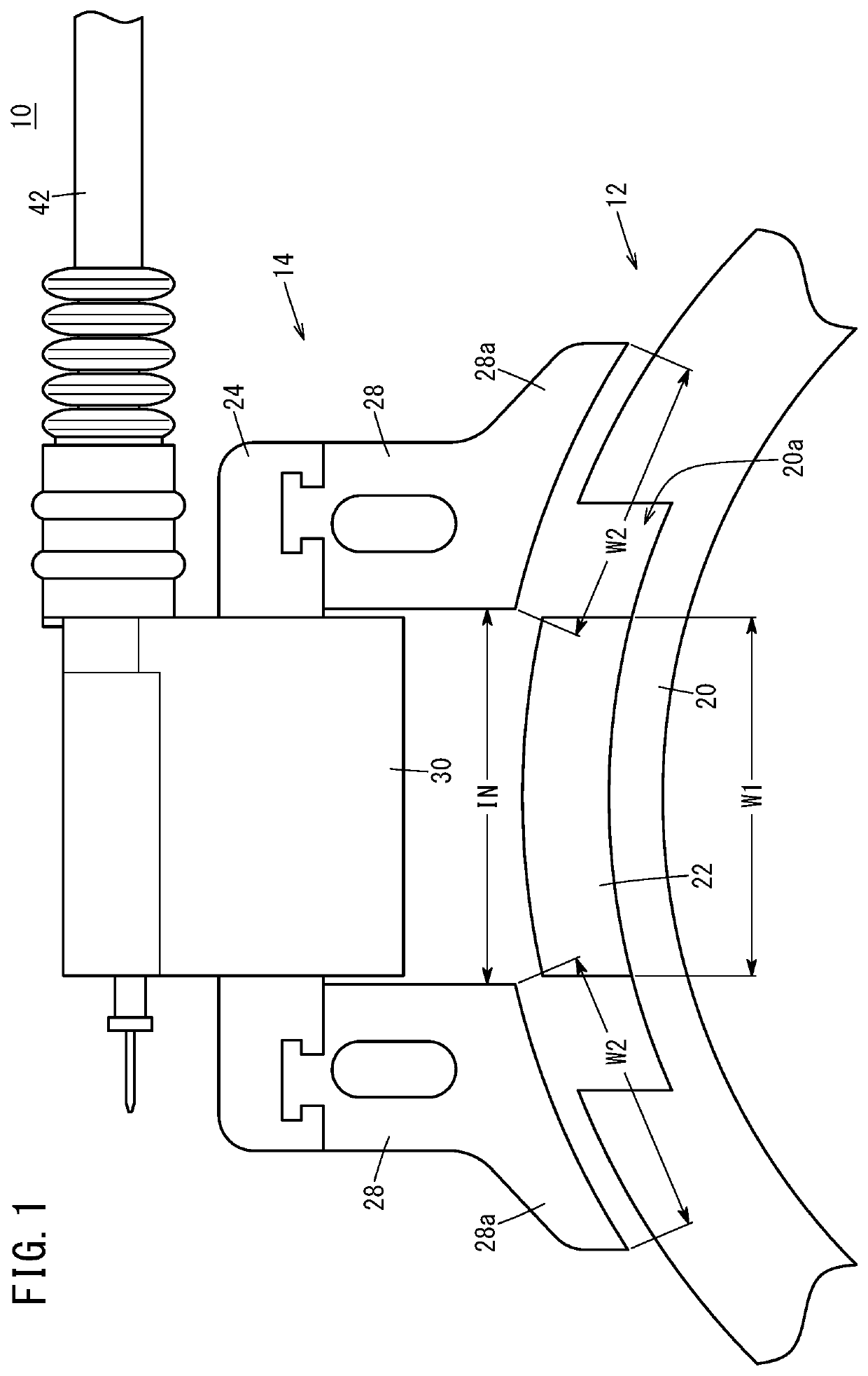
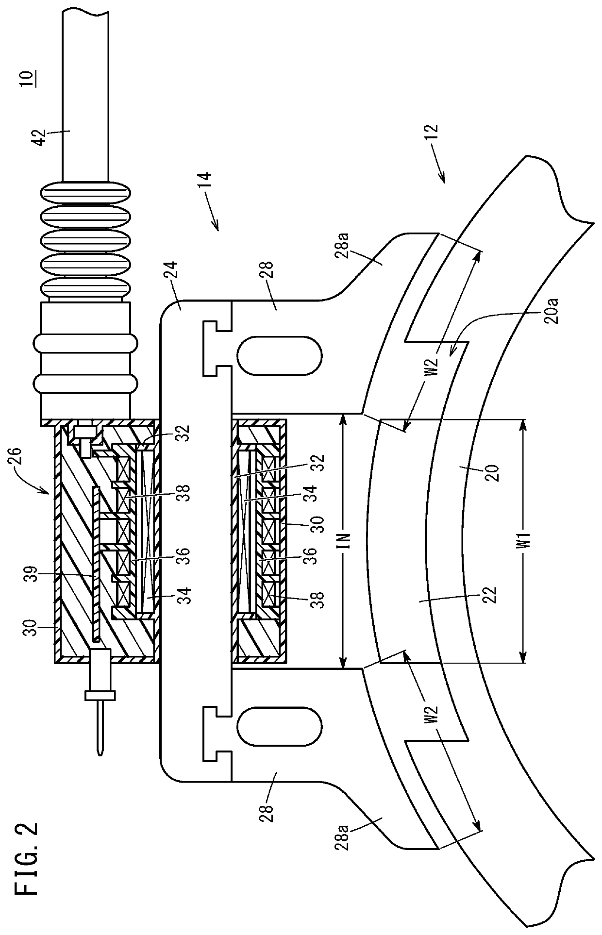
[0048]In Example 1, under the condition that the proportion of the yoke end width W2 to the magnet width W1 was fixed to 70%, waveforms of the primary voltage when the proportions of the magnet width W1 to the yoke interval IN were 105%, 97.5%, and 90% were measured. FIG. 6 shows the measurement results. The primary voltage waveforms shown in FIG. 6 were measured while the ignition drive circuit 56 was not provided with the primary current limiter section 78.
[0049]As illustrated in FIG. 6, the primary voltage waveform obtained when the proportion of the magnet width W1 to the yoke interval IN was 90% had a lower sub voltage than the primary voltage waveform obtained when the proportion was 97.5%. On the other hand, the primary voltage waveform obtained when the proportion of the magnet width W1 to the yoke interval IN was 105% had a narrower peak width in a main voltage and a smaller advanced angle range than the primary voltage waveform obtained when the proportion was 97....
example 2
[0052]In Example 2, under the condition that the proportion of the magnet width W1 to the yoke interval IN was fixed to 100%, waveforms of the primary voltage when the proportions of the yoke end width W2 to the magnet width W1 were 40%, 60%, 80%, and 100% were measured. FIG. 7 shows the measurement results. It is noted that, in the primary voltage waveforms shown in FIG. 7, the horizontal axis represents the mechanical angle (°), and measurement was performed while the ignition drive circuit 56 was provided with the primary current limiter section 78. Thus, the shapes of the primary voltage waveforms shown in FIG. 7 slightly differ from the shapes of the primary voltage waveforms shown in FIG. 6.
[0053]In FIG. 7, an ignition control range θw is a region in which enough main voltage for ignition can be secured, that is, a mechanical angle range in which ignition control is enabled at any point. As shown in FIG. 7, in the primary voltage waveforms obtained when the proportions of the ...
PUM
 Abstract
Description
Claims
Application Information
 - R&D
- Intellectual Property
- Life Sciences
- Materials
- Tech Scout
- Unparalleled Data Quality
- Higher Quality Content
- 60% Fewer Hallucinations
Browse by: Latest US Patents, China's latest patents, Technical Efficacy Thesaurus, Application Domain, Technology Topic, Popular Technical Reports.
© 2025 PatSnap. All rights reserved.Legal|Privacy policy|Modern Slavery Act Transparency Statement|Sitemap|About US| Contact US: help@patsnap.com


