Floor element for forming a floor covering, a floor covering, and a method for manufacturing a floor element

a technology of floor elements and floor coverings, which is applied in the field of floor elements, can solve the problems of affecting the propagation of resin, and achieve the effects of improving the impact resistance of the floor element, reducing the impact stress, and improving the transmission and dissipation of impact stress

Active Publication Date: 2020-01-09
DALTILE CORP
View PDF3 Cites 12 Cited by
  • Summary
  • Abstract
  • Description
  • Claims
  • Application Information

AI Technical Summary

Benefits of technology

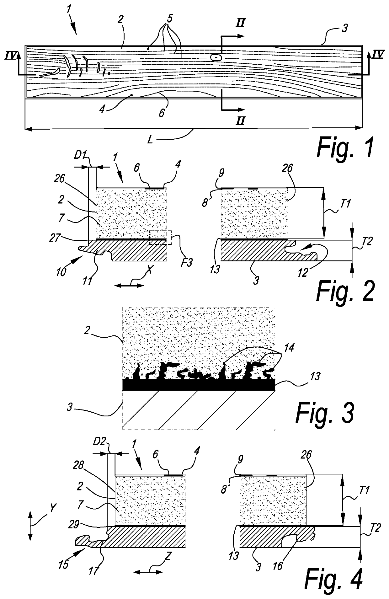
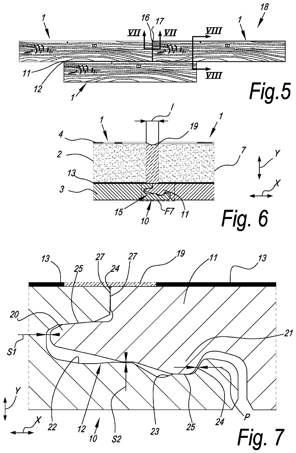
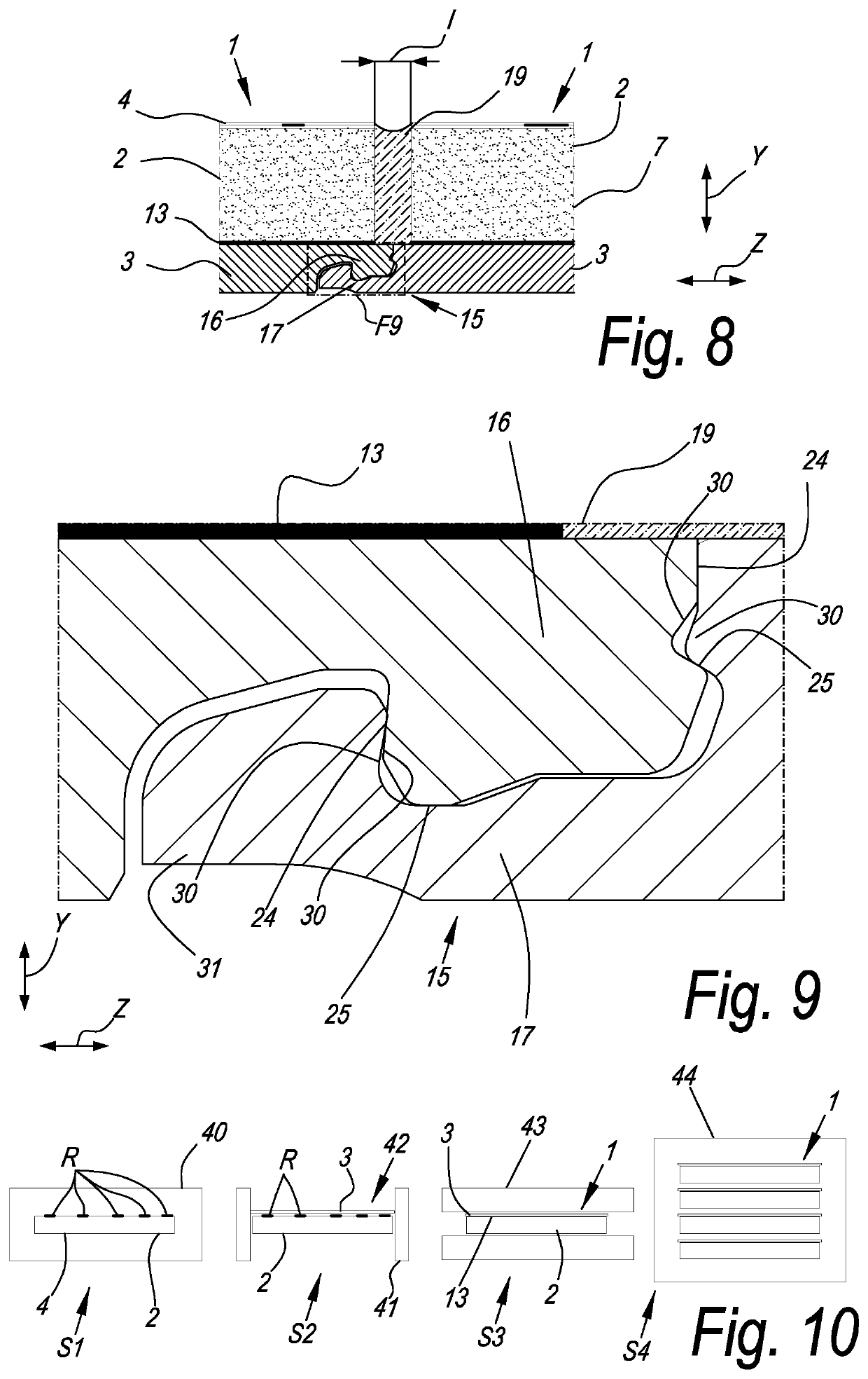
[0009]Thereto, the present invention, according to its first independent aspect, relates to a floor element for forming a floor covering, wherein this floor element comprises a decorative layer made of a ceramic material and a support layer arranged below this decorative layer, wherein the support layer comprises edges provided with coupling elements configured to realize a mechanical coupling with coupling elements of an adjacent floor element and wherein the floor element comprises an intermediate layer having a resin material that permeates a lower surface of the decorative layer. The inventors have found that, thanks to this solution, the impact resistance of the floor element, more particularly of the decorative layer of ceramic, is highly increased, so that, even with the mechanical locking between such floor elements, the impact strength achieves or even exceeds the impact strength of the traditional elements installed by means of adhesiv

Problems solved by technology

Moreover, the resin constitutes a hinder to the pr

Method used


Image

  • Floor element for forming a floor covering, a floor covering, and a method for manufacturing a floor element
  • Floor element for forming a floor covering, a floor covering, and a method for manufacturing a floor element
  • Floor element for forming a floor covering, a floor covering, and a method for manufacturing a floor element

Examples


Embodiment Construction

[0093]To facilitate an understanding of the principles and features of the various embodiments of the invention, various illustrative embodiments are explained below. Although exemplary embodiments of the invention are explained in detail as being systems and methods for cleanable and slip resistant tile, it is to be understood that other embodiments are contemplated, such as embodiments employing other types of surfaces, coatings, tiles, or tile manufacturing methods. Accordingly, it is not intended that the invention is limited in its scope to the details of construction and arrangement of components set forth in the following description or examples. The invention is capable of other embodiments and of being practiced or carried out in various ways. Also, in describing the exemplary embodiments, specific terminology will be resorted to for the sake of clarity.

[0094]It must also be noted that, as used in the specification and the appended claims, the singular forms “a,”“an” and “t...


PUM

PropertyMeasurementUnit
Temperatureaaaaaaaaaa
Weightaaaaaaaaaa
Fractionaaaaaaaaaa

Abstract

A floor element for forming a floor covering, wherein the floor element comprises a decorative layer made of a ceramic material and a support layer arranged below this decorative layer, wherein the support layer comprises edges provided with coupling elements configured to allow a mechanical coupling with coupling elements of an adjacent floor element and wherein the floor element comprises an intermediate layer having a resin material that permeates a lower surface of the decorative layer.

Description

BACKGROUND1. Field[0001]The present invention relates to a floor element for forming a floor covering, a floor covering, and a method for manufacturing a floor element.More particularly, the invention is related to a floor element for forming a floor covering, wherein this floor element comprises a decorative layer made of a brittle material such as natural stone, glass or sintered ceramic materials like porcelain, earthenware or the like. The decorative layer can, for example, be a ceramic tile.2. Background[0002]Traditionally, ceramic tiles are installed by laying them side by side on a surface such as a floor or wall. Typically, an adhesive compound is used to attach the tiles to the surface. Seams between the tiles are grouted. In this way, the tiles are bonded to a rigid surface, for example a concrete subfloor, thereby improving their impact strength. The bound with the subfloor, and thus also with the structure of the dwelling, also leads to a high attenuation of walking soun...

Claims


Application Information

Patent Timeline
IPC IPC(8): E04F15/08E04F15/02B32B3/06B32B7/12B32B9/00B32B27/06B32B27/30B32B37/12
CPCB32B2471/00B32B27/06E04F2201/043B32B7/12B32B37/12E04F2201/023E04F15/0215B32B9/005B32B2307/402B32B3/06B32B27/304E04F15/082B32B2255/00E04F15/02038E04F2201/042E04F15/087E04F2201/0146E04F2201/0153B32B9/045B32B38/08B32B2250/02B32B2255/26B32B2260/02B32B2260/046B32B2307/546B32B2307/718B32B2307/732B32B2309/04B32B2309/12B32B2315/02B32B2327/06B32B2451/00E04F15/107
Inventor PATKI, RAHULCASELLI, CLAUDIO
Owner DALTILE CORP
Why Eureka
Try Eureka