
Holographic display device having reduced chromatic aberration

a display device and chromatic aberration technology, applied in the field of holographic display devices, can solve the problems of limited viewpoints, tired viewers, and inability to increase the number of viewpoints, and achieve the effect of reducing chromatic aberration

Active Publication Date: 2020-01-09
SAMSUNG ELECTRONICS CO LTD
View PDF0 Cites 0 Cited by
  • Summary
  • Abstract
  • Description
  • Claims
  • Application Information

AI Technical Summary

Benefits of technology

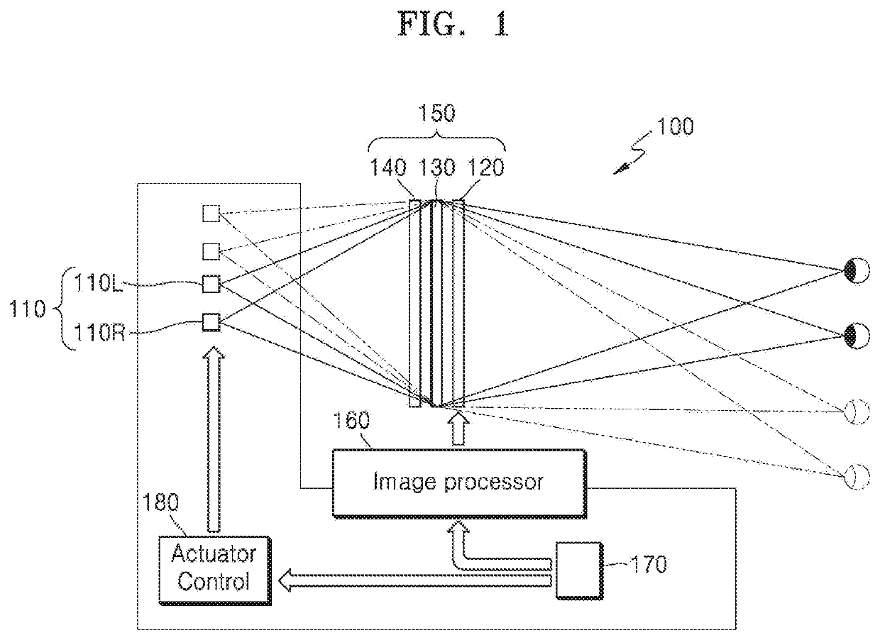
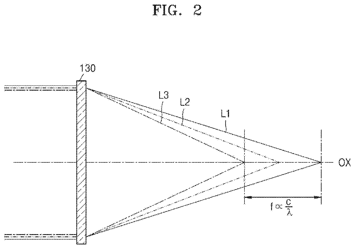
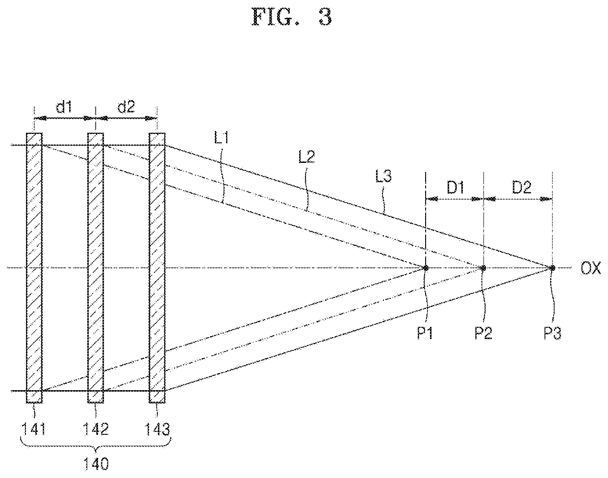
The patent describes a holographic display device that reduces chromatic aberration. The device includes a light source, a spatial light modulator, and a focusing optical system. The focusing optical system includes a fixed-focus optical system and a variable focus optical system. The fixed-focus optical system focuses light of different wavelengths on different positions on the optical axis to cancel chromatic aberration. The variable focus optical system has a focal length that can be adjusted by electrical control to focus light of different wavelengths on the same position. The device also includes a hologram pattern that is formed by the light source, a fixed-focus optical system, and a variable focus diffractive lens element. The fixed-focus optical system includes a first lens set and a second lens set, and the variable focus optical system includes a third lens set. The device can be used to produce high-quality holograms and can be used in various applications such as holographic displays and optical sensors.

Problems solved by technology

These methods use binocular parallax, and increasing the number of viewpoints is limited.
In addition, these methods may make the viewers feel tired due to the difference between the depth perceived by the brain and the depth of focus by the eyes.

Method used


Image

  • Holographic display device having reduced chromatic aberration
  • Holographic display device having reduced chromatic aberration
  • Holographic display device having reduced chromatic aberration

Examples


Embodiment Construction

[0049]Hereinafter, a holographic display device having reduced chromatic aberration will be described in detail with reference to the accompanying drawings. The same reference numerals refer to the same elements throughout. In the drawings, the sizes of constituent elements may be exaggerated for clarity. The example embodiments described below are merely exemplary, and various modifications may be possible from the example embodiments. In a layer structure described below, an expression such as “above” or “on” may include not only the meaning of “immediately on / under / to the left / to the right in a contact manner”, but also the meaning of “on / under / to the left / to the right in a non-contact manner”.

[0050]As used herein, the term “and / or” includes any and all combinations of one or more of the associated listed items. It will be further understood that the terms “comprises” and / or “comprising” used herein specify the presence of stated features or elements, but do not preclude the pres...


PUM


Abstract

A holographic display device includes a light source configured to emit light, the light including first light of a first wavelength, second light of a second wavelength, and third light of a third wavelength; a spatial light modulator configured to form a holographic pattern to modulate the light emitted from the light source and to produce a holographic image; and a focusing optical system configured to focus the holographic image. The focusing optical system includes a fixed-focus optical system having a fixed focal length, and a variable focus optical system having a focal length that is changed by electrical control. The fixed-focus optical system is configured to focus the first light of the first wavelength, the second light of the second wavelength, and the third light of the third wavelength on different positions, respectively, on an optical axis to cancel a chromatic aberration by the variable focus optical system.

Description

CROSS-REFERENCE TO RELATED APPLICATION[0001]This application claims priority from Korean Patent Application No. 10-2018-0077619, filed on Jul. 4, 2018 in the Korean Intellectual Property Office, the disclosure of which is incorporated herein in its entirety by reference.BACKGROUND1. Field[0002]Example embodiments of the present disclosure relate to a holographic display device, and more particularly, to a holographic display device having reduced chromatic aberration.2. Description of the Related Art[0003]Methods of realizing three-dimensional (3D) images such glasses-type methods and non-glasses-type methods are widely used. Examples of glasses-type methods include polarizing glasses-type methods and shutter glasses-type methods, and examples of the non-glasses-type methods include lenticular methods and parallax barrier methods. These methods use binocular parallax, and increasing the number of viewpoints is limited. In addition, these methods may make the viewers feel tired due t...

Claims


Application Information

Patent Timeline
Patent Type & Authority Applications(United States)
IPC IPC(8): G02B27/00G02B7/09G03H1/22
CPCG03H2001/2234G03H2222/13G03H2222/34G02B27/0037G03H2223/22G02B27/0068G03H2223/16G02B27/0093G03H1/2205G03H1/2286G02B7/09G03H2223/23G03H1/2294G03H2001/221G03H2222/18G03H2222/31G03H2223/17G03H2226/05G03H1/04
Inventor SONG, HOONLEE, HONGSEOKKIM, YOUNGAN, JUNGKWUENWON, KANGHEECHOI, CHILSUNG
Owner SAMSUNG ELECTRONICS CO LTD
Learn More