Input power supply selection circuit

a selection circuit and input power supply technology, applied in emergency power supply arrangements, pulse techniques, instruments, etc., can solve the problems of increasing the size and cost of the input power supply selection circuit, the design complexity of the related circuit, and the switch malfunction, so as to reduce the switching capacity requirements of the load switch, simplify the contact protection design, and reduce the switching capacity requirements

Active Publication Date: 2020-01-09
MURATA MFG CO LTD
View PDF0 Cites 7 Cited by
  • Summary
  • Abstract
  • Description
  • Claims
  • Application Information

AI Technical Summary

Benefits of technology

[0022]Each of the preferred embodiments of the present disclosure provide at least one of the following benefits.
[0023]In preferred embodiments of the present disclosure, the input power supply selection circuit includes a load switch branch to control the load to be connected or disconnected at an appropriate opportunity. According to the voltage of the at least one input power, the output voltage of the input selection circuit, and the load voltage, the sensing and control module controls the input selection circuit to switch the operation power supply for the load and controls the load switch branch to be connected or disconnected. Therefore, the input selection switches in the input selection circuit maintain a zero current state during the power switching, thus simplifying a contact protection design and reducing the switching capacity requirements. The hybrid design including semiconductors and mechanical relays in the load switch branch also greatly reduces the switching capacity requirements of the load switch.
[0024]Further, the sensing and control module determines whether the input selection circuit functions normally by comparing a voltage of the operation power supply with the output voltage of the input selection circuit to protect against electrical hazards.

Problems solved by technology

Overheating of the switch and a contact sticking may be caused, which may result in a malfunction of the switch.
Therefore, it is necessary to set a relay switch in the input power supply selection circuit, however, this increases a size and cost of the input power supply selection circuit and a design complexity of the related circuit.

Method used


Image

  • Input power supply selection circuit
  • Input power supply selection circuit
  • Input power supply selection circuit

Examples


Embodiment Construction

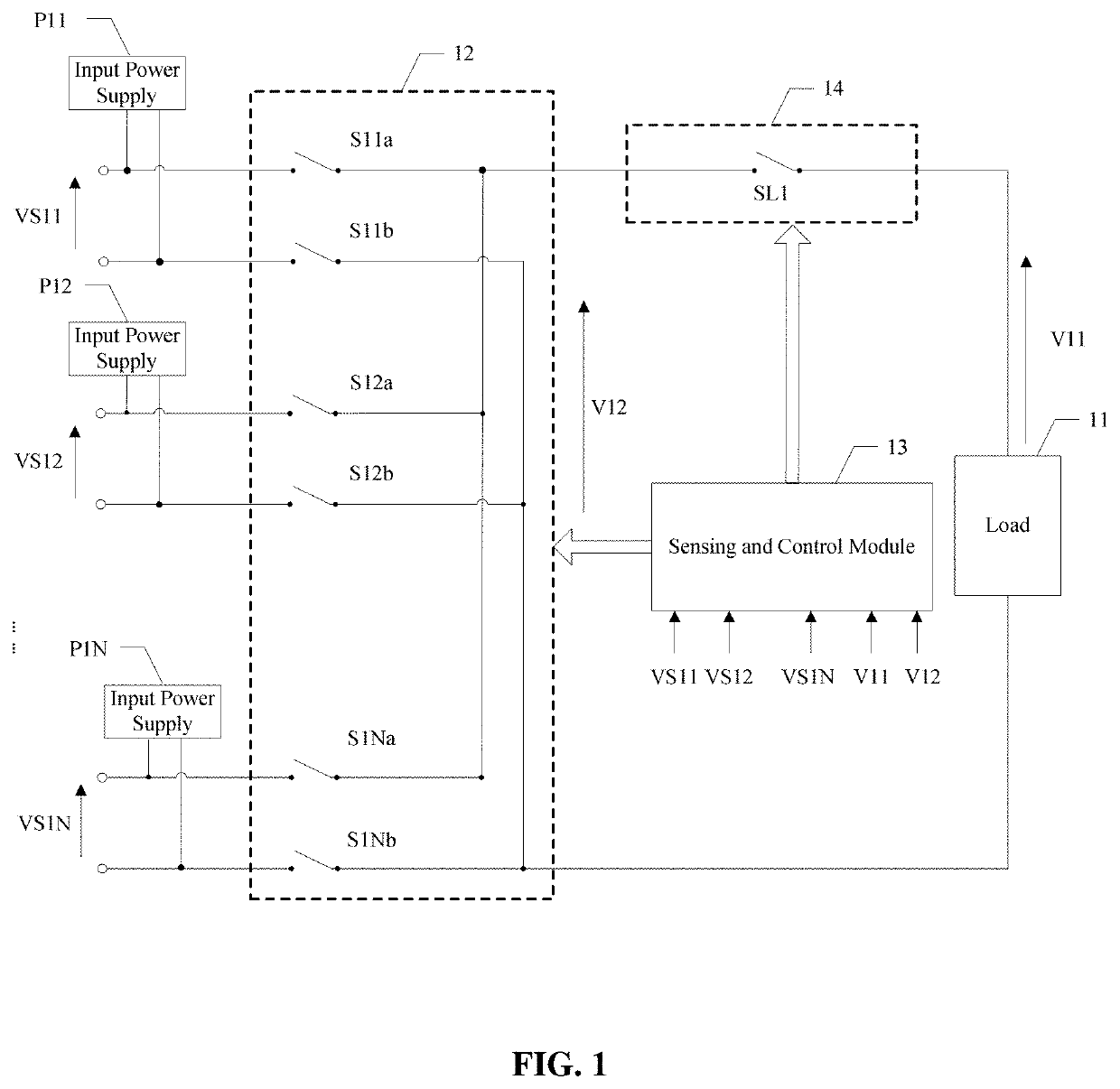
[0027]FIG. 1 schematically illustrates a structural diagram of an input power supply selection circuit according to a preferred embodiment of the present disclosure. The input power supply selection circuit includes a load 11, at least one input power supply (P11-P1N), an input selection circuit 12, a sensing and control module 13, and a load switch branch 14.

[0028]In some preferred embodiments, the at least one input power supply (P11-P1N) is configured to provide an operation power supply for the load 11 and the sensing and control module 13, the input selection circuit 12 is configured to select one of the at least one input power supply (P11-P1N) as the operation power supply for the load, wherein the operation power supply is a DC (direct current) power supply or a AC (alternating current) power supply. The sensing and control module 13 is configured to control the input selection circuit 12 to switch the operation power for the load 11 according to voltages (VS11-VS1N) of the ...


PUM


Abstract

An input power supply selection circuit includes a load, at least one input power supply to provide an operation power supply for the load, an input selection circuit to select the at least one input power supply as the operation power supply for the load, a sensing and control module to control the input selection circuit to switch the operation power supply for the load, and a load switch branch to control the load to be connected or disconnected. The sensing and control module controls the load switch branch to be connected or disconnected, and when the load switch branch is disconnected, the load and the at least one input power supply are not electrically coupled. Therefore, a contact protection design is simplified and a switching capacity requirement of the load switch branch is lowered.

Description

CROSS REFERENCE TO RELATED APPLICATIONS[0001]This application claims the benefit of priority to Chinese Patent Application No. 201810735303.6, filed on Jul. 5, 2018, the entire disclosure of which is incorporated herein by reference.BACKGROUND OF THE INVENTION1. Field of the Invention[0002]The present disclosure relates to an integrated circuit field, and more particularly, to an input power supply selection circuit.2. Description of the Related Art[0003]A certain power supply system is provided with more than one input power supply for redundancy. An input power supply selection circuit coupled to the power supply system usually includes a plurality of relay switches, and selects one of input power supplies for the operation of the power supply system. When a selected input power supply is determined to be problematic, the sensing and control module switches the problematic input power supply to a normal one to maintain operation of the power supply system.[0004]If the power supply...

Claims


Application Information

Patent Timeline
Patent Type & Authority Applications(United States)
IPC IPC(8): H02J9/06H02M3/155H02M1/08
CPCH02M3/155H02J9/06H02M1/08H02J1/00H02J1/10H02J3/0073H02J9/068H02H9/002H03K17/082H02J3/007H02J1/084H02J2310/12H02H3/20H02H3/28Y04S20/20
Inventor LIU, CHUI PONG
Owner MURATA MFG CO LTD
Why Eureka
Try Eureka