Optical scanning system

a scanning system and optical scanning technology, applied in the field of optical scanning systems, can solve the problem that the transmission beam cannot be expanded, and achieve the effect of high degree of sensitivity of the optical scanning system, optical scanning, and convenient optimization

Active Publication Date: 2020-01-23
ROBERT BOSCH GMBH
View PDF0 Cites 3 Cited by
  • Summary
  • Abstract
  • Description
  • Claims
  • Application Information

AI Technical Summary

Benefits of technology

[0014]In addition, it is advantageous if the optical receive unit includes a first mirror, the first mirror being configured such that the reflected scanning beam is deflected onto the detector by the first mirror after running through the lens. In this way, it is made possible for a receive beam path to find space between the lens and the detector, because this beam path is folded by the first mirror. Depending on the configuration of the optical components of the receive unit, it is advantageous if the optical receive unit includes additional lenses and mirrors.
[0015]In addition, it is advantageous if the first mirror has a focusing surface, in particular a vaulted surface. The first mirror is thus curved. In this way, aberrations of the lens can be partly compensated.
[0016]In addition, it is advantageous if the optical transmit unit has an optical emitter and a second mirror, the second mirror being configured in such a way that the scanning beam sent out by the optical emitter is diverted by the second mirror in the direction of the optical axis of the lens. The optical emitter is preferably a laser, in particular a laser diode. Such a configuration of a second mirror makes it possible for only the second mirror, but not the overall optical emitter, to be situated before the lens. In this way, a maximum useful surface of the lens is achieved. This results in a high degree of sensitivity of the optical scanning system.
[0017]In addition, it is advantageous if the optical transmit unit includes a collimation lens. In this way, the collimation lens is integrated into the optical scanning system in a space-saving manner. In this way, the optical scanning system can be easily optimized for a particular scanning distance. Here, the collimation lens is in particular a lens of a lens system through which a single scanning beam or a plurality of scanning beams are collimated.
[0018]It is also advantageous if the optical receive unit and / or the optical transmit unit includes an optical filter. Through such filters, the sensitivity of the optical scanning system can be achieved while the small constructive shape is maintained.
[0019]In particular, it is advantageous if the optical scanning system is a coaxial macroscanner.

Problems solved by technology

A disadvantage of the approach describer therein is that the transmission beam cannot be expanded up to a maximum lens diameter and simultaneously collimated, which would be advantageous for increased transmit power and thus an increased range, while simultaneously ensuring eye safety.

Method used


Image

  • Optical scanning system
  • Optical scanning system
  • Optical scanning system

Examples


Embodiment Construction

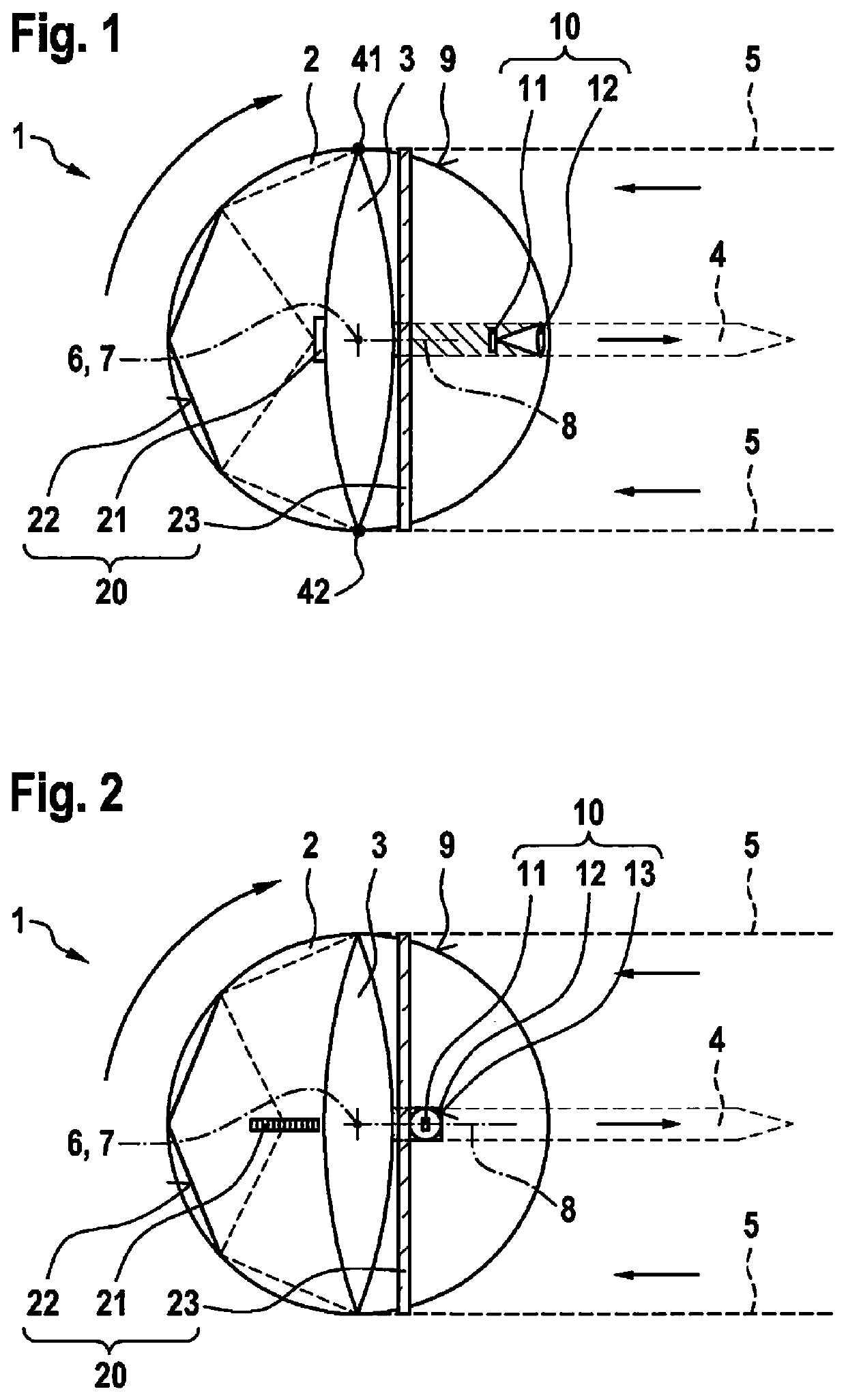
[0026]FIG. 1 shows an optical scanning system 1 according to a first specific embodiment of the present invention. Here, optical scanning system 1 is shown in a sectional image along a first sectional plane. An axis of rotation of the optical scanning system stands perpendicular to the depicted first sectional plane.

[0027]Optical scanning system 1 is a coaxial macroscanner. This means that a scanning beam 4 that is sent out by optical scanning system 1 has an axis that is parallel—in this first specific embodiment, identical—to that of a reflected scanning beam 5 that is received by optical scanning system 1. Optical scanning system 1 includes a rotor 2, an optical lens 3, an optical transmit unit 10, and an optical receive unit 20.

[0028]Rotor 2 is set up to rotate about an axis of rotation 6 during a scanning process. In this first specific embodiment of the present invention, rotor 2 is a circular disk and axis of rotation 6 stands perpendicular to a circular surface of rotor 2, r...


PUM


Abstract

An optical scanning system is described, including a rotor that is set up to rotate about an axis of rotation during a scanning process, an optical lens that is situated on the rotor in such a way that the lens is situated on the axis of rotation, an optical transmit unit that is situated on the rotor and is set up to send out a scanning beam in the direction of an optical axis of the lens, and an optical receive unit that is situated on the rotor and includes a detector that is set up to receive a reflected scanning beam, the detector being situated such that the reflected scanning beam is focused onto the detector by the lens.

Description

FIELD[0001]The present invention relates to an optical scanning system.BACKGROUND INFORMATION[0002]Current scanning systems, in particular biaxial rotating 3-D laser scanners, so-called macroscanners, in which the optical axes of the transmit and receive units run parallel to one another at a certain distance from one another, have a certain constructive size. This holds both for macroscanners in which a mirror or mirror system rotates and for macroscanners in which the transmit and receive units are situated parallel to one another on the rotor.[0003]However, for integration in particular environments, for example in vehicle headlights, a particularly flat constructive shape having a low constructive height and having a small rotor diameter is advantageous. An approach for reducing the constructive size of a macroscanner is to guide the transmission beam path and reception beam path partly through the same lens. Because as a result the optical axes of the transmit unit and receive ...

Claims


Application Information

Patent Timeline
Patent Type & Authority Applications(United States)
IPC IPC(8): G01S7/481G02B26/08G02B26/10
CPCG02B26/0875G01S7/4817G01S7/4812G02B26/10
Inventor SPARBERT, JANBOGATSCHER, SIEGWARTHASSELBACH, JUERGENHAS, REMIGIUS
Owner ROBERT BOSCH GMBH
Why Eureka
Try Eureka