Terminal metal fitting and terminal-attached electric wire

a terminal-attached electric wire and metal fitting technology, which is applied in the direction of electrical equipment, connections, and permanent deformation-induced connections, can solve the problems of loosing the barrel portion, usually difficult to bring an intermediate portion, so as to improve the reliability of the electrical connection of the entire terminal-attached electric wir

Inactive Publication Date: 2020-01-23
YAZAKI CORP
View PDF1 Cites 0 Cited by
  • Summary
  • Abstract
  • Description
  • Claims
  • Application Information

AI Technical Summary

Benefits of technology

[0029]In particular, whereas the thickness of a base portion, crimped onto the cover body of an electric wire, of a barrel portion is, in general, about the same as the outer diameter of the electric wire, a tip portion, crimped onto a terminal portion of a conductor core wire, of the barrel portion is, in general, thinner than the tip portion. It is considered that it is usually difficult to bring an intermediate portion, connecting the base portion and the tip portion that are different from each other, of the barrel portion into close contact with the conductor core wire. In contrast, in the terminal-attached electric wire having the above configuration in which the bent portion is formed in the intermediate portion, the adhesion between the intermediate portion and the conductor core wire is increased, whereby the reliability of the electrical connection of the entire terminal-attached electric wire is made higher.
[0030]Thus, in the terminal-attached electric wire having the above configuration, the reliability of the electrical connection between the conductor core wire of the electric wire and the terminal metal fitting can be kept at a proper level.
[0031]The invention makes it possible to provide a terminal metal fitting and a terminal-attached electric wire capable of keeping the reliability of the electrical connection between a conductor core wire of an electric wire and the terminal metal fitting at a proper level.

Problems solved by technology

However, in the above conventional terminal-attached electric wire, there may occur an event that the state that the barrel portion is in pressure contact with the conductor core wire satisfactorily due to, for example, repetition of expansion and contraction of the terminal metal fitting or the conductor core wire caused by temperature variations or aging deterioration due to long term use, resulting in loosening of the barrel portion.
It is considered that it is usually difficult to bring an intermediate portion, connecting the base portion and the tip portion that are different from each other, of the barrel portion into close contact with the conductor core wire.

Method used


Image

  • Terminal metal fitting and terminal-attached electric wire
  • Terminal metal fitting and terminal-attached electric wire
  • Terminal metal fitting and terminal-attached electric wire

Examples


embodiment

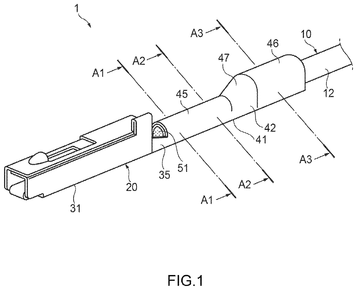
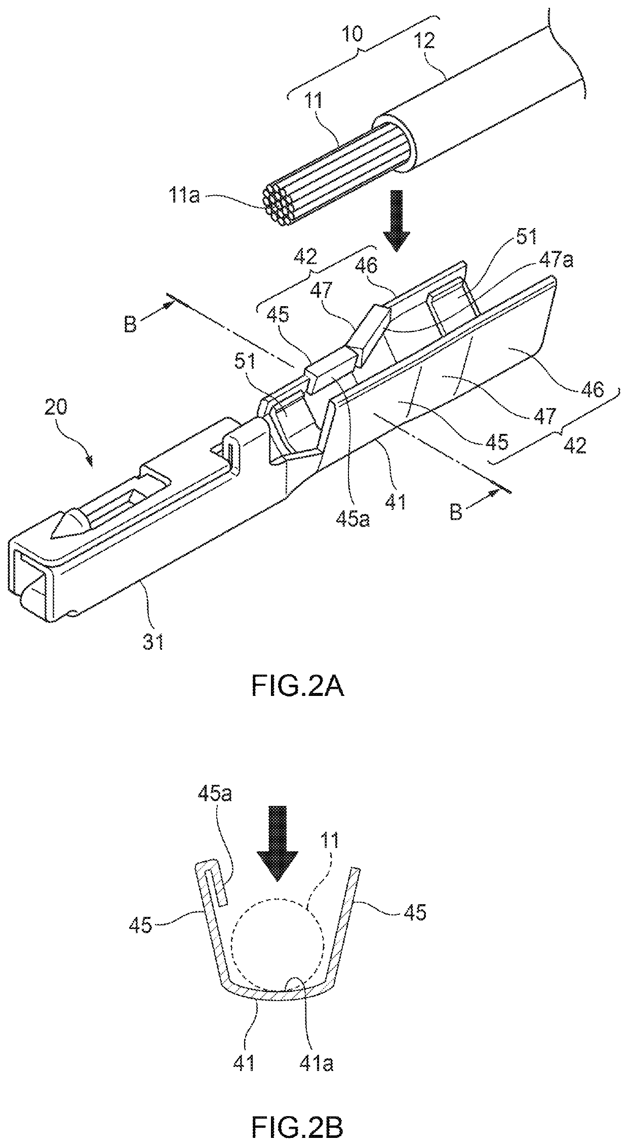
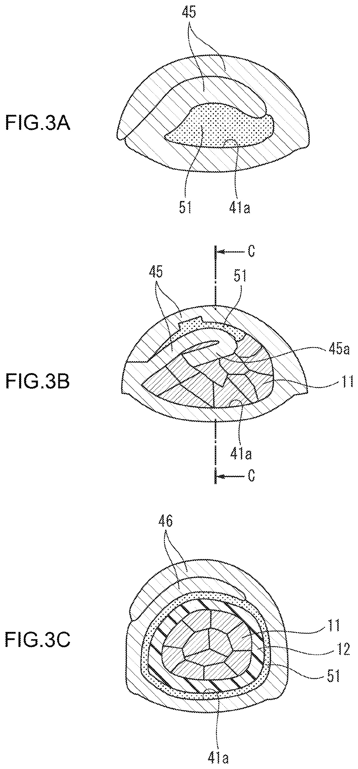
[0039]A terminal-attached electric wire 1 in which a terminal metal fitting 20 according to an embodiment of the present invention is attached to an electric wire 10 will be hereinafter described with reference to the drawings. In the following, for convenience of description, in the axial direction (fitting direction) of the terminal metal fitting 20, the side of fitting with a counterpart terminal (not shown), that is, the left side in FIGS. 1, 2A, and 4, will be referred to as a tip side (front side) and the side opposite to it, that is, the right side in FIGS. 1, 2A, and 4, will be referred to as a base side (rear side). Furthermore, the top side and the bottom side are defined as seen in FIGS. 1, 2A, and 4.

[0040]As shown in FIGS. 1-4, the terminal metal fitting 20 is crimped on an end portion of the electric wire 10 and thereby electrically connected to a conductor core wire 11 of the electric wire 10. The electric wire 10 and the terminal metal fitting 20 constitute the termin...


PUM


Abstract

A terminal metal fitting (20) includes a barrel portion (41) and a contact portion (31). The barrel portion (41) has a plate body to be formed into a tubular shape by overlapping its one end and its other end each other. The plate body has: a base portion (46); a tip portion (45); and an intermediate portion (47) connecting the base portion (46) and the tip portion (45) and to cover a conductor core wire (11) located between the base portion (46) and the tip portion (45). The barrel portion (41) has, at the one end portion of at least the intermediate portion (47) among the plate body, a bent portion (47a) having a bent shape toward the conductor core wire (11) before crimping and to be in pressure contact with the conductor core wire (11) after the crimping.

Description

CROSS-REFERENCES TO RELATED APPLICATION(S)[0001]This application is based on and claims priority from Japanese Patent Application No. 2018-137568 filed on Jul. 23, 2018, and the entire contents of which are incorporated herein by reference.TECHNICAL FIELDField of the Invention[0002]The present invention relates to a terminal metal fitting and a terminal-attached electric wire in which a terminal metal fitting is attached to an electric wire.Description of Related Art[0003]In recent years, terminal-attached electric wires in which a terminal metal fitting made of copper or a copper alloy is attached to an electric wire having a conductor core wire made of aluminum or an aluminum alloy (hereinafter referred to as an “aluminum electric wire”) have come to be used in, for example, wire harnesses routed in a vehicle from the viewpoints of weight reduction etc.[0004]For example, in one conventional terminal-attached electric wire using an aluminum electric wire, the surface of a barrel po...

Claims


Application Information

Patent Timeline
Patent Type & Authority Applications(United States)
IPC IPC(8): H01R4/18
CPCH01R4/185H01R4/184H01R4/188
Inventor SATO, KEI
Owner YAZAKI CORP
Why Eureka
Try Eureka