
Methods and instrumentation for detection of transverse rolling contact fatigue rail defects within head-hardened rail

Active Publication Date: 2020-01-30
FRIEND RODNEY
View PDF0 Cites 0 Cited by
  • Summary
  • Abstract
  • Description
  • Claims
  • Application Information

AI Technical Summary

Benefits of technology

The patent text proposes a search unit that can detect internal web floors in a single pass. The acoustic transducer is positioned to prevent signal attenuation caused by horizontal lamination defects. The search unit has a base surface that matches the contour of the web, reducing the likelihood of such problems.

Problems solved by technology

According to the Handbook, squat defects are of concern because there has been a considerable increase in their numbers over the past 4-6 years.
Further according to the Handbook there is a danger that the secondary or minor sub-surface cracks (illustrated in FIG. 50 of the Handbook) may turn down and grow on a transverse plane similarly to transverse defects, with the possibility of resulting in a broken rail if not detected in time.
These transverse defects 107 compromise the structural integrity of the rail 100.
Problematically, reflections of horizontal lamination defects 106 prevent or hinder the detection of these transverse defects 107 using conventional acoustic penetration detection methods, a problem referred to in the industry as “loss of bottom” signals.
Specifically, according to C5-4 of the Handbook, the horizontal subsurface primary cracks will cause shielding of the ultrasonic signals from deeper defects during normal ultrasonic inspections.
As such, 60 kg head-hardened rail is currently considered untestable for transverse defects.

Method used


Image

  • Methods and instrumentation for detection of transverse rolling contact fatigue rail defects within head-hardened rail
  • Methods and instrumentation for detection of transverse rolling contact fatigue rail defects within head-hardened rail
  • Methods and instrumentation for detection of transverse rolling contact fatigue rail defects within head-hardened rail

Examples


Embodiment Construction

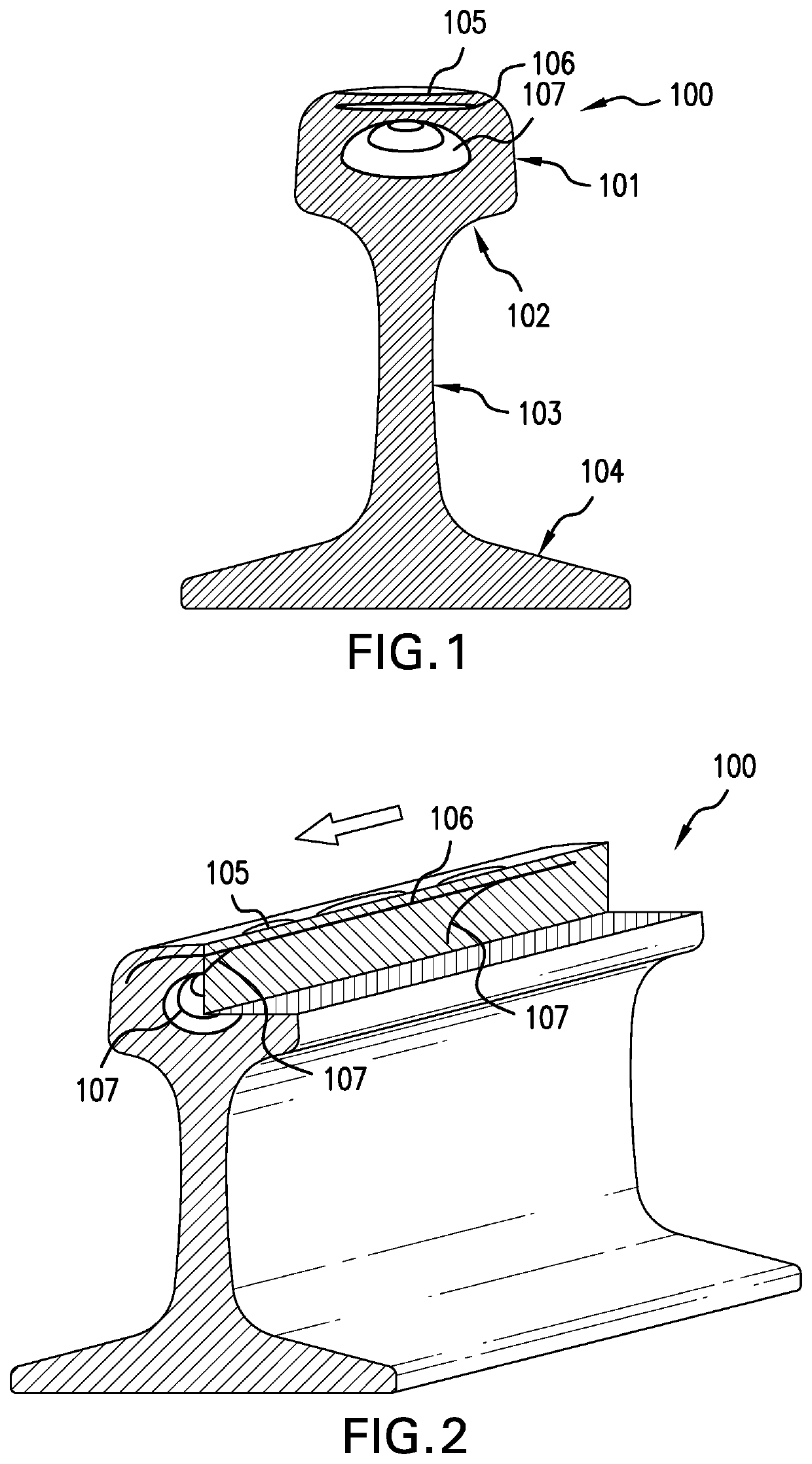
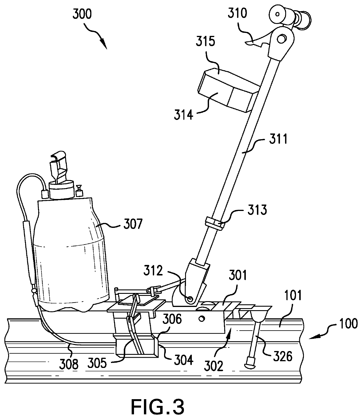
[0075]FIGS. 3 and 4 shows detection instrumentation 300 for detection of transverse rail defects 107 in accordance with an embodiment.

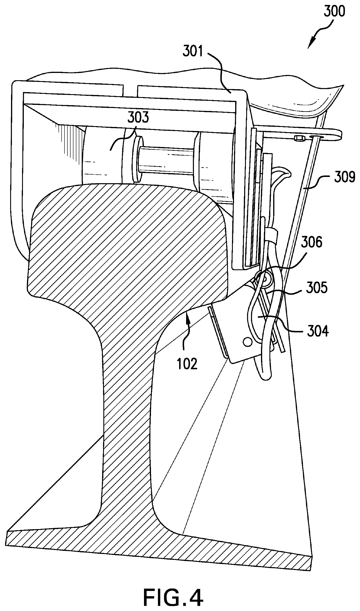
[0076]The instrumentation 300 comprises a bogey 301 defining a channel 302 thereunderneath that travels across the head 101 of the rail 100 on bearings 303.

[0077]The bogey 301 supports a single pulse-echo acoustic (such as piezoelectric) transducer 300 which may be mounted on a swing arm 305 from one side of the bogey 301. The transducer 304 is directed at the fillet 102 of the rail 103 at approximately 45° so as to be able to direct and receive acoustic signals into and from the railhead 101. The transducer 304 may comprise a convex wear face 306 so as to conform with the concave profile of the fillet 102 for enhancing signal propagation. A reservoir 307 may feed coupling agent via a hose in advance of the wear face 306 for further enhancing acoustic signal propagation.

[0078]The bogey 301 may be pushed along the rail utilising a handle 311 which may ...


PUM


Abstract

There is provided detection instrumentation for the detection of transverse rail defects in rail head hitherto considered untestable on account of acoustic signal attenuation problems of horizontal lamination defects. The detection instrumentation comprises a pulse-echo acoustic transducer having a wear face for contacting a fillet of the rail and being aimed towards a head of the rail such that the transmitter transmits acoustic signals into the head and the receiver receives acoustic signals reflected at differing depths within the head. A signal receiver operably coupled to the receiver times the acoustic signals according to a timeseries railhead depth position scale. Analysis of the depth positions of the reflected acoustic signals according to relative positioning of the instrumentation along the rail may identify the transverse rail defects

Description

FIELD OF THE INVENTION[0001]This invention relates generally to rolling contact fatigue detection. More particularly, this invention relates to methods and instrumentation configured for identifying a specific type of defect within head-hardened rail, being a transverse rail defect, hitherto considered undetectable on account of acoustic signal attenuation of horizontal lamination defects which typically occur along with transverse rail defects.[0002]The embodiments provided herein make reference primarily to 60 kg head-hardened rail which is increasingly being employed for high traffic demand rail sections. However, it should be appreciated that the embodiments provided herein may be applicable for other types of rail within the purposive scope of the embodiments described herein.BACKGROUND OF THE INVENTION[0003]FIGS. 1 and 2 show respective cross-sectional and perspective views of 60 kg head-hardened rail 100, comprising a head 101, a head-web transition fillet 102, a web 103 and ...

Claims


Application Information

Patent Timeline
IPC IPC(8): G01N29/11G01N29/04G01N29/44
CPCG01N2291/015G01N29/4445G01N2291/0258G01N29/043G01N2291/044G01N29/11G01N2291/2623G01N29/00G01N29/04
Inventor FRIEND, RODNEY
Owner FRIEND RODNEY
Features
  • Generate Ideas
  • Intellectual Property
  • Life Sciences
  • Materials
  • Tech Scout
  • Unparalleled Data Quality
  • Higher Quality Content
  • 60% Fewer Hallucinations
Learn More