Detector arrangement for an x-ray phase contrast system and method for x-ray contrast imaging

Active Publication Date: 2020-01-30
KONINKLJIJKE PHILIPS NV
View PDF0 Cites 0 Cited by
  • Summary
  • Abstract
  • Description
  • Claims
  • Application Information

AI Technical Summary

Benefits of technology

[0014]By adapting the optical grating to the phase grating of the system the optical grating may be provided having an optimum pitch for the optimum imaging quality. In a certain example, the optical grating comprises a pitch being

Problems solved by technology

The technical design requirements for G2 are challenging.
Furt

Method used


Image

  • Detector arrangement for an x-ray phase contrast system and method for x-ray contrast imaging
  • Detector arrangement for an x-ray phase contrast system and method for x-ray contrast imaging
  • Detector arrangement for an x-ray phase contrast system and method for x-ray contrast imaging

Examples


Embodiment Construction

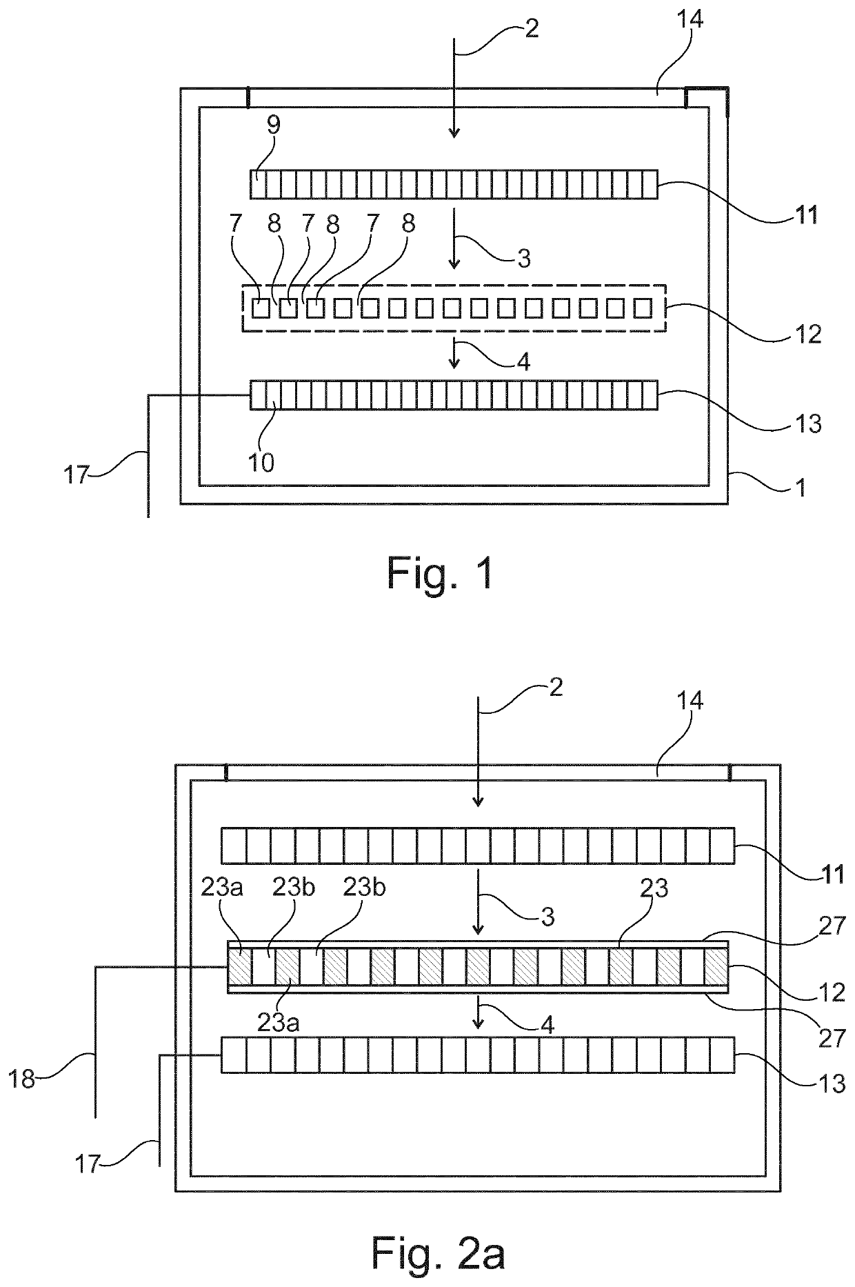
[0030]FIG. 1 shows an embodiment of a detector arrangement 1. The detector arrangement 1 comprises an X-ray transparent wall 14, a conversion unit, a subsampling unit, and a detection unit. The subsampling unit is arranged between the conversion unit and the detection unit.

[0031]The X-ray transparent wall 14 serves as inlet for X-ray radiation 2. In an example, the X-ray transparent wall 14 may be an opening in a side wall of the detector arrangement 1. In another example, the X-ray transparent wall 14 may be a massive wall being made from an X-ray transparent material.

[0032]The conversion unit comprises a plurality of conversion elements 9 being configured to convert X-ray radiation 2 into optical radiation resulting in optical radiation 3. In an example, the conversion unit is a high-resolution scintillator 11 having a pitch between 0.5 μm and 60 μm. The X-ray radiation 2 impacting the scintillator 11 is converted to optical radiation 3 by the scintillator 11. Thus, the scintillat...


PUM


Abstract

The present invention relates to a detector arrangement for an X-ray phase contrast system (5), the detector arrangement (1) comprising: a scintillator (11); an optical grating (12); and a detector (13); wherein the optical grating (12) is arranged between the scintillator (11) and the detector (13); wherein the scintillator (11) converts X-ray radiation (2) into optical radiation (3); wherein the IN optical grating (12) is configured to be an analyzer grating being adapted to a phase-grating (21) of an X-ray phase contrast system (5); wherein the optical path between the optical grating (12) and the scintillator (11) is free of focussing elements for optical radiation. The present invention further relates to a method (100) for performing X-ray phase contrast imaging with a detector arrangement (1) mentioned above. The invention avoids the use of an X-ray absorption grating as G2 grating in an X-ray phase contrast interferometer system.

Description

FIELD OF THE INVENTION[0001]The present invention relates to a detector arrangement and a system for an X-ray phase contrast system, and a method for X-ray phase contrast imaging.BACKGROUND OF THE INVENTION[0002]X-ray phase contrast imaging may be performed using Talbot-Lau type interferometers. Talbot-Lau type interferometer for differential phase contrast and dark field imaging are using a setup of gratings to obtain low angle scattering and differential phase information from the X-ray refraction. The so-called G2 grating is e.g. an analyzer grating to subsample the wave pattern in front of the X-Ray detector. The term “subsample” refers to that only distinct periodically arranged parts of the wave front are propagated and not absorbed. The technical design requirements for G2 are challenging. The G2 should have a small pitch between 2 μm to 50 μm. The absorber in the grating should be high-Z to have sufficient X-ray stopping power. This yields a high aspect ratio requirement. Fu...

Claims


Application Information

Patent Timeline
IPC IPC(8): G01T1/20G21K1/06G21K1/16G21K4/00
CPCG21K2207/005G01T1/2006G21K2004/06G01T1/2002G21K2201/067G21K1/16G21K1/067G21K4/00G21K1/025G01T1/00G01N23/041
Inventor PROKSA, ROLAND
Owner KONINKLJIJKE PHILIPS NV
Why Eureka
Try Eureka