Anti-theft sign bracket and sign assembly and method

a technology for anti-theft signs and brackets, which is applied in the direction of display means, buildings, instruments, etc., can solve the problems of inability to easily engage the end slots of the elongated molded element with the undulations of the ballistic fence, and difficulty in accessing the brackets

Active Publication Date: 2020-01-30
UTILITY COMPLIANCE CONSULTANTS LLC
View PDF6 Cites 0 Cited by
  • Summary
  • Abstract
  • Description
  • Claims
  • Application Information

AI Technical Summary

Benefits of technology

[0019]The sign can be loosely bolted to a bracket either before or after the bracket is secured to the fence. If the sign is loosely bolted to each of a plurality of sign-supporting brackets before the brackets are secured to the fence, the tie strips can be inserted through slots in the fence and their locking heads engaged with their remote portions. The bolts and tie strips can then be tightened in any desired order. By bolting the sign to the brackets before attachment of the brackets to the fence, difficulties in aligning the bolts with the nuts inside the brackets can be avoided.

Problems solved by technology

The brackets and the bolt holes in the sign are typically located inboard relative to the edges of the sign to make access to the brackets difficult after the bolts are tightened.
Thus the sign can be secured to a chain link fence in such a way that a thief not equipped with special tools will encounter a considerable amount of difficulty in attempting to remove the sign.
That is, the end slots in the elongated molded element cannot be readily engaged with the undulations of the ballistic fence.

Method used


Image

  • Anti-theft sign bracket and sign assembly and method
  • Anti-theft sign bracket and sign assembly and method
  • Anti-theft sign bracket and sign assembly and method

Examples


Embodiment Construction

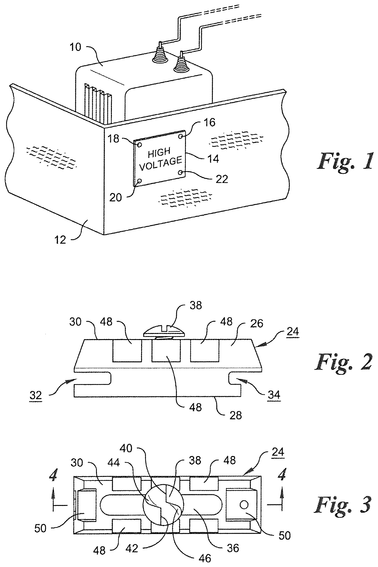
[0029]In the electrical utility installation illustrated in FIG. 1, a utility transformer 10 is protected by a ballistic fence 12. A sign 14, for example a warning sign, which is typically, although not necessarily, in the form of a rectangular panel, is attached to the ballistic fence. Four bolts, 16, 18, 20 and 22, located adjacent the respective corners of the sign, extend though the panel and are affixed to the ballistic fence by bracket assemblies (not shown in FIG. 1) which will be described with reference to FIGS. 2-8.

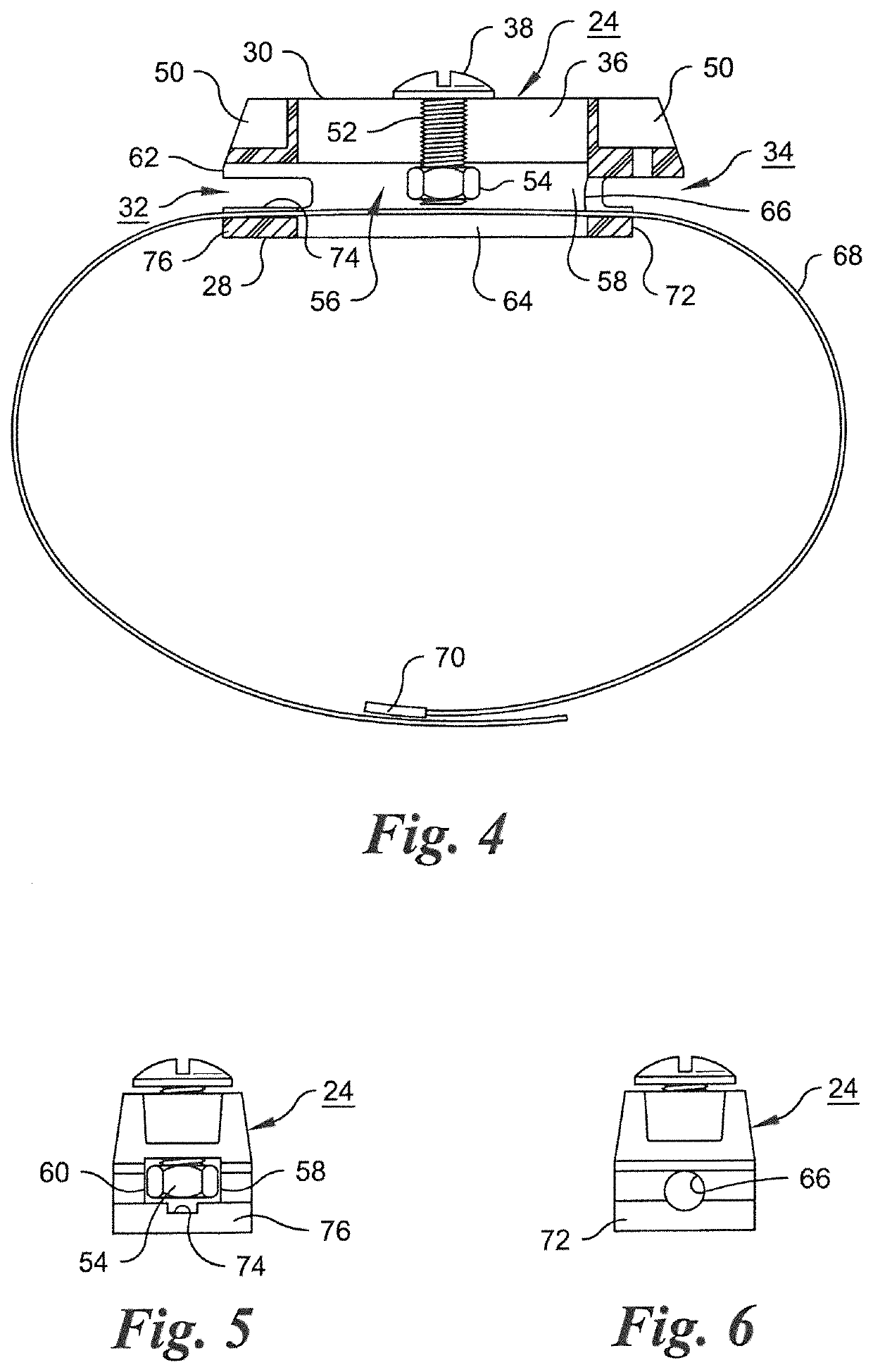
[0030]The bracket member 24, as shown in FIG. 2, comprises a rigid element 26, preferably molded from a suitable synthetic resin such as a polyamide resin, an acetal polymer, or an acrylonitrile-butadiene-styrene polymer. The rigid element 26 is formed with a first outer surface 28 for abutting engagement with an outer face of the ballistic fence 12 shown in FIG. 1. Rigid element 26 is formed with a second, outer surface 30 for abutting engagement with a back su...


PUM


Abstract

A theft-resistant sign bracket for use with a ballistic fence comprises a bracket member having a slot for a one-way bolt used to secure a sign to the bracket, an internal space, elongated in the direction of elongation of the slot, for receiving and preventing rotation of a nut engaged with the shank of the bolt while allowing positioning of the nut and bolt at a desired location along the slot, and a metal tie strip extending through an internal passage in the bracket and capable of being passed through two spaced openings in the ballistic fence for securing the bracket to the fence. One or more grooves formed in the space through which the tie strip extends prevent lateral movement of the bracket relative to the tie strip.

Description

FIELD OF THE INVENTION[0001]This invention relates generally to sign-supporting brackets, and more specifically to a theft-resistant sign assembly, incorporating a bracket, wherein a sign, including a banner or the like, is secured to a face of a ballistic fence, i.e., a fence capable of stopping or resisting penetration by projectiles.BACKGROUND OF THE INVENTION[0002]One known form of theft-resistant sign bracket is a bracket comprising an elongated element molded from a synthetic resin. A bolt extends through an elongated slot in the molded element and is engaged with a nut located in a nut-receiving space within the molded element, the nut-receiving space being elongated along the direction of elongation of the slot. The nut is slidable in the direction of elongation of the slot but restrained against rotation by opposed internal walls of the nut-receiving space. The bolt is a “one-way” bolt, having a receptacle formed in its head for receiving the tip of a screwdriver. The recep...

Claims


Application Information

Patent Timeline
Patent Type & Authority Applications(United States)
IPC IPC(8): G09F7/18E04H17/16
CPCE04H17/16G09F7/18G09F2007/1856
Inventor KEELER, PAUL
Owner UTILITY COMPLIANCE CONSULTANTS LLC
Why Eureka
Try Eureka