Fast plane-wave reverse time migration

Inactive Publication Date: 2020-02-06
SAUDI ARABIAN OIL CO
View PDF0 Cites 1 Cited by
  • Summary
  • Abstract
  • Description
  • Claims
  • Application Information

AI Technical Summary

Benefits of technology

The present invention provides a better way to get and process seismic traces from a seismic survey to get an image of the underground structure. The method involves converting the seismic traces to a different form and then using a technique called reverse time migration to create the image. This makes it easier to see the underground structure and helps with drilling wells in the subsurface.

Problems solved by technology

Seismic data analysis is complex because the recorded data is the result of interrelated physical processes and noise.
Reverse time migration has traditionally been considered impractical in part to high computational costs.
Conventional plane-wave reverse time migration suffers from long delay time problems.
The problem results from the time difference in activation time between the first and last source in a plane-wave gather.
This problem greatly increases the computation cost of plane-wave reverse time migration and hinders its application and practice in industry.
Nevertheless, solving the wave equation by finite differencing computer processing in reverse time migration, solving the time domain Green's function and storing the results still has, so far as is known, proven very expensive in terms of computation processing time.
The described technique was also apparently time-consuming in terms of computer processing time, since trade-offs in accuracy of results were provided as alternatives to processing time and complexity.

Method used


Image

  • Fast plane-wave reverse time migration
  • Fast plane-wave reverse time migration
  • Fast plane-wave reverse time migration

Examples


example individual

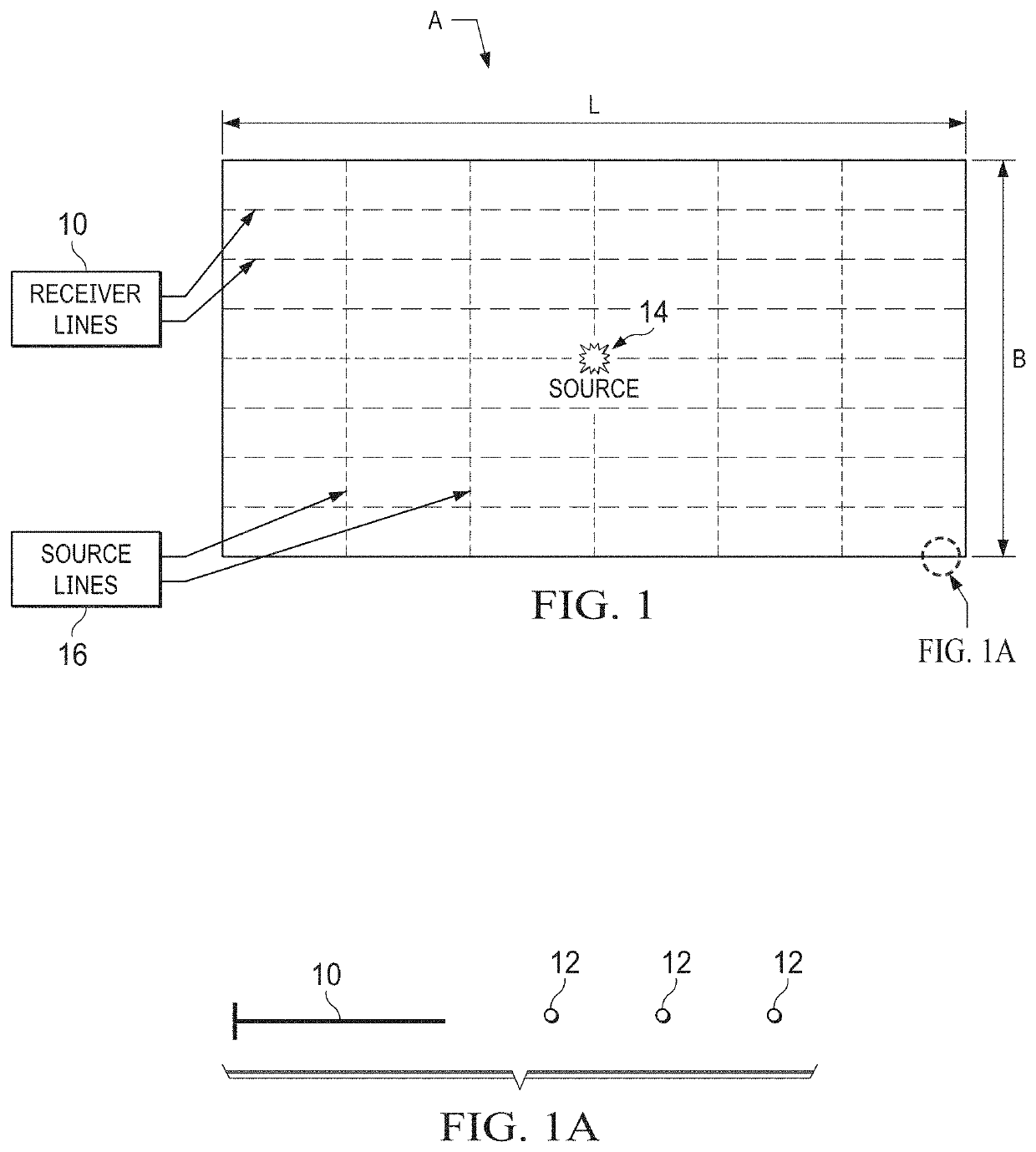
[0027 ones of a number of spaced seismic energy receivers 12 are shown schematically along survey lines 10, each such line composed of the spaced receivers 12 as indicated schematically in FIG. 1A. The individual receivers 12 are geophones mounted at fixed locations in the array A for land surveys and hydrophones for surveys in bodies of water.

[0028]During seismic survey operations, a source of energy such as one shown schematically at 14 (FIG. 1) is activated or fired into the ground by seismic sources positioned along source lines 16 at a number of particular locations over the array A according to a survey plan. Each individual instance of source activation known as a “shot”. The energy from a seismic survey shot is a non-periodic time decaying impulse signal which propagates as a pressure wave and as a shear wave through the ground.

[0029]The propagating seismic energy pressure wave is reflected from structures in the underlying geology. The reflected return energy is measured by...


PUM


Abstract

Reverse time migration (RTM) performed on plane-wave seismic exploration survey results avoids long delay time problems in processing of plane-wave reverse time migration. The plane-wave sources and gathers are wrapped periodically, which significantly reduces computation cost of plane-wave reverse time migration. Circular convolution is performed without having to determine in advance the exact signals being convolved. Computer resources for preparing and storing the two signals in advance are significantly reduced from those previously required.

Description

BACKGROUND OF THE INVENTION1. Field of the Invention[0001]The present invention relates to geophysics, and more particularly to acquisition and processing of seismic survey results in order to more accurately indicate subsurface formation structure from reverse time migration of the survey results, and to thus determine areas of interest for drilling wells.2. Description of the Related Art[0002]For determining areas of interest for drilling wells in subsurface formations, analysis of the results of seismic exploration surveys plays an important part. The seismic survey results when properly analyzed indicate formations of interest, whether on land or offshore.[0003]Seismic data analysis is complex because the recorded data is the result of interrelated physical processes and noise. Velocity models of the formation being explored in areas of interest are employed due to simulate the acquired data. The velocity models are representations of wave propagation velocity inside the formati...

Claims


Application Information

Patent Timeline
IPC IPC(8): G01V1/30G01V1/32G01V1/28E21B49/00
CPCG01V1/282E21B49/00G01V1/301G01V2210/679E21B47/0002G01V1/32G01V2210/614E21B47/002
Inventor XIONGWEN, WANGYI, LUOHONGWEI, LIU
Owner SAUDI ARABIAN OIL CO
Why Eureka
Try Eureka