Ball valve positioning structure
- Summary
- Abstract
- Description
- Claims
- Application Information
AI Technical Summary
Benefits of technology
Problems solved by technology
Method used
Image

Examples
Embodiment Construction
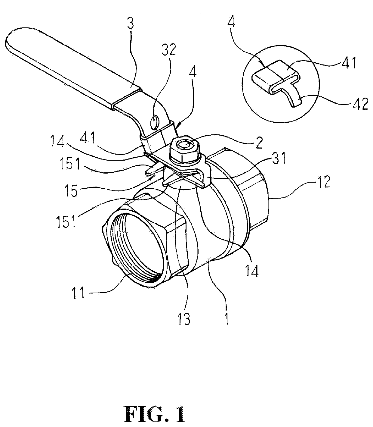
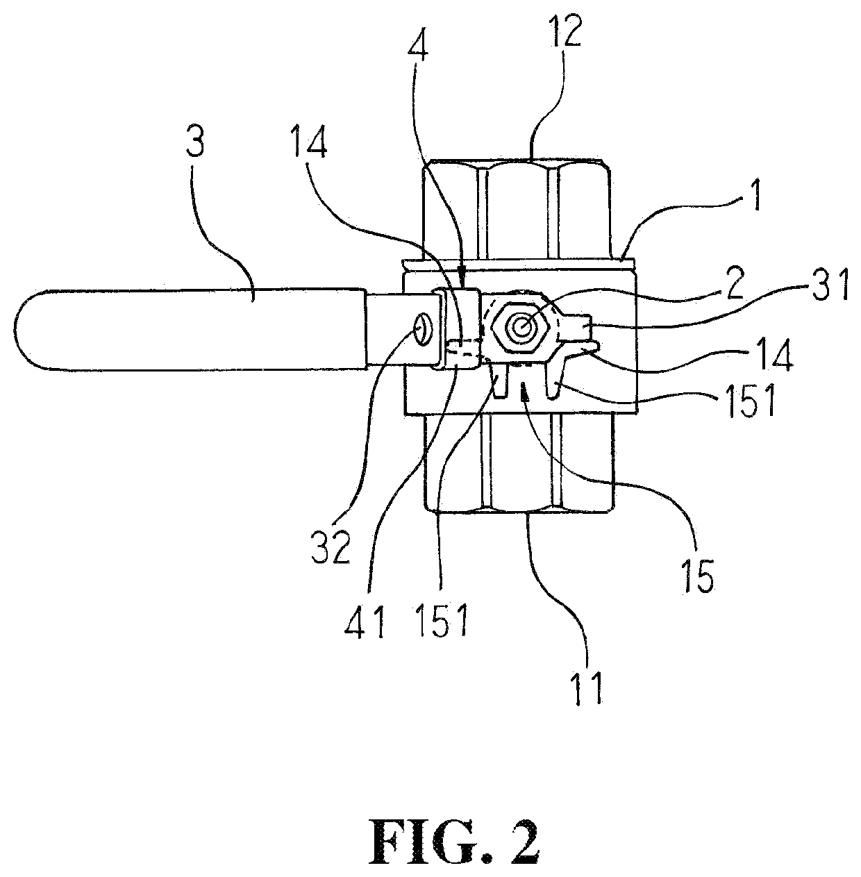
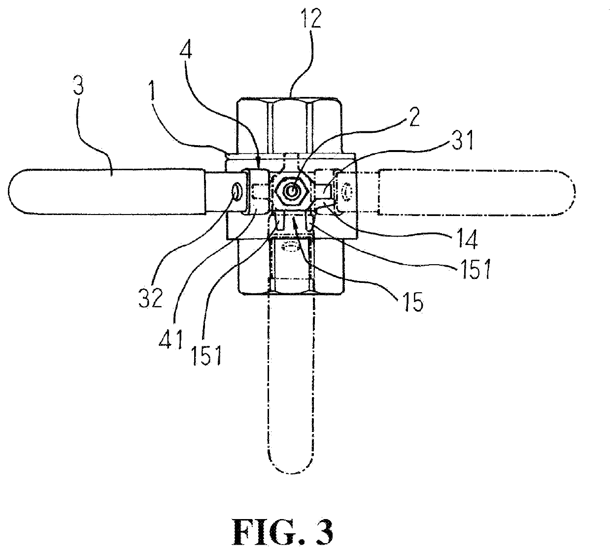
[0015]Referring to FIGS. 1 and 2, a ball valve positioning structure of the present invention includes a main body 1, rotating shaft 2 and handle 3.
[0016]The main body 1 is configured with a water entrance 11 and water exit 12, where one end of the water entrance 11 and one end of the water exit 12 are respectively formed with a thread connection end so as to facilitate the connection with pipes of different types. The upper side of the main body 1 is configured with a housing aperture 13, the circumference of which is respectively configured with two stop levers 14 and a fastening portion 15. In a preferred embodiment, the two stop levers 14 are perpendicular to the water entrance 11 and water exit 12, and the fastening portion 15 is two symmetrically arranged rods 151 which are positioned in the same direction as the water entrance 11 and water exit 12. The inside of the main body 1 is configured with a ball having an opening; when the ball is rotated 90 degrees, a spherical face ...
PUM
 Abstract
Description
Claims
Application Information
 - Generate Ideas
- Intellectual Property
- Life Sciences
- Materials
- Tech Scout
- Unparalleled Data Quality
- Higher Quality Content
- 60% Fewer Hallucinations
Browse by: Latest US Patents, China's latest patents, Technical Efficacy Thesaurus, Application Domain, Technology Topic, Popular Technical Reports.
© 2025 PatSnap. All rights reserved.Legal|Privacy policy|Modern Slavery Act Transparency Statement|Sitemap|About US| Contact US: help@patsnap.com