
An actuator device incorporating an electroactive polymer actuator and a driving method

a technology of electroactive polymer actuator and actuator device, applied in piezoelectric/electrostrictive device details, piezoelectric/electrostrictive/magnetostrictive devices, device details, etc., can solve the problem of high operation voltage, high current, and low field (volts per meter) requirements, so as to improve the lifetime of eap materials and less accurate charge monitoring

Active Publication Date: 2020-02-13
KONINKLJIJKE PHILIPS NV
View PDF0 Cites 1 Cited by
  • Summary
  • Abstract
  • Description
  • Claims
  • Application Information

AI Technical Summary

Benefits of technology

The device described in this patent uses a special type of actuator that is controlled by current instead of voltage. This allows for real-time adjustments to compensate for any mechanical differences in how the actuator operates. The device also includes a circuit to prevent damage to the actuator and ensure accurate monitoring of the charge. These adjustments make it easier to operate the actuator with a current source or voltage control, which would be more efficient and accurate in certain situations.

Problems solved by technology

They require high fields (volts per meter) but low currents due to their capacitive nature.
In the case of dielectric elastomers, the Maxwell stress induced by the applied electric field results in a stress on the film, causing it to contract in thickness and expand in area.
One problem with field driven electroactive polymers is the rather high operation voltages that are required, as mentioned above, to achieve high electric field strengths in the devices to realize desired deflections.
Driving voltage amplitudes of up to lkV are required for these EAPs, so that high voltage devices need to be used and implemented, increasing the cost (and size) of the electronics enormously.
This of course would result in unacceptable offsets in particular applications where very precise actuation levels need to be reached in a very reliable way.
Both solutions require enormous overhead either in terms of costs and / or space and / or processing power, etc.

Method used


Image

  • An actuator device incorporating an electroactive polymer actuator and a driving method
  • An actuator device incorporating an electroactive polymer actuator and a driving method
  • An actuator device incorporating an electroactive polymer actuator and a driving method

Examples


Embodiment Construction

[0057]The invention provides a field-driven electroactive polymer actuator which is provided with a current sensor for sensing a current flowing to the actuator. A control circuit is used for driving the actuator which includes a voltage source. The driving of the actuator is controlled in dependence on the sensed current, thereby to provide a predetermined current delivery for particular changes in actuation level of the actuator. This provides a combined voltage-based and current-based drive scheme for a voltage-driven EAP actuator, and it enables mechanical movements of the actuator to be more reliably repeated.

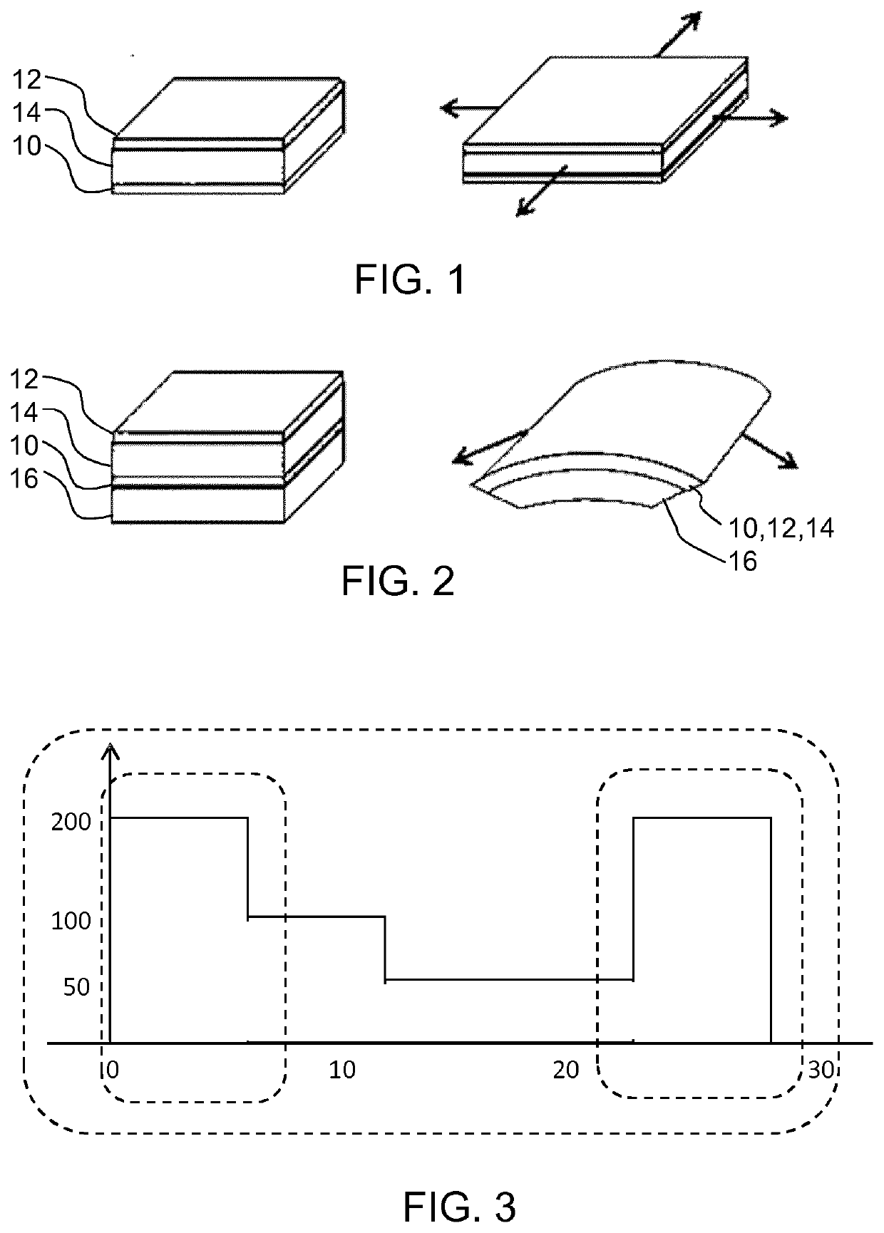
[0058]In general terms, field driven electroactive polymer (EAP) actuators consist of an electrically isolating material, embedded between two electrically conducting electrodes. As a function of an applied voltage, the electric field between the electrodes causes a mechanical deformation of the EAP. As explained above, by using additional materials with a different extens...


PUM


Abstract

A field-driven electroactive polymer actuator is provided with a current sensor for sensing a current flowing to the actuator. A control circuit is used for driving the actuator which includes a voltage source. The driving of the actuator is controlled in dependence on the sensed current, thereby to provide a predetermined charge delivery for particular changes in actuation level of the actuator. This provides a combined voltage-based and current-based drive scheme for a voltage-driven EAP actuator, and it enables mechanical movements of the actuator to be more reliably repeated.

Description

FIELD OF THE INVENTION[0001]This invention relates to electroactive polymer actuators.BACKGROUND OF THE INVENTION[0002]Electroactive polymers (EAPs) are an emerging class of materials within the field of electrically responsive materials. EAPs can work as sensors or actuators and can easily be manufactured into various shapes allowing easy integration into a large variety of systems.[0003]Materials have been developed with characteristics such as actuation stress and strain which have improved significantly over the last ten years. Technology risks have been reduced to acceptable levels for product development so that EAPs are commercially and technically becoming of increasing interest. Advantages of EAPs include low power, small form factor, flexibility, noiseless operation, accuracy, the possibility of high resolution, fast response times, and cyclic actuation.[0004]The improved performance and particular advantages of EAP materials give rise to applicability to new applications....

Claims


Application Information

Patent Timeline
Patent Type & Authority Applications(United States)
IPC IPC(8): H01L41/04H01L41/193H01L41/09H10N30/80H10N30/20H10N30/50H10N30/857
CPCH01L41/042H01L41/193H01L41/09H10N30/802H10N30/204H10N30/857H10N30/50H10N30/20
Inventor HILGERS, ACHIMJOHNSON, MARK THOMASVAN DEN ENDE, DAAN ANTON
Owner KONINKLJIJKE PHILIPS NV
Learn More