Blower spray device

a spray device and blower technology, applied in the field of blower spray devices, can solve the problems of insufficient adjustment of air flow velocity, relative noise, exhaust gas generation, etc., and achieve the effect of efficient and environmentally friendly us

a spray device and blower technology, applied in the field of blower spray devices, can solve the problems of insufficient adjustment of air flow velocity, relative noise, exhaust gas generation, etc., and achieve the effect of efficient and environmentally friendly us

US20200054000A1Pending Publication Date: 2020-02-20BIRCHMEIER SPRUHTECHN

Image

  • Blower spray device
  • Blower spray device
  • Blower spray device

Examples


Embodiment Construction

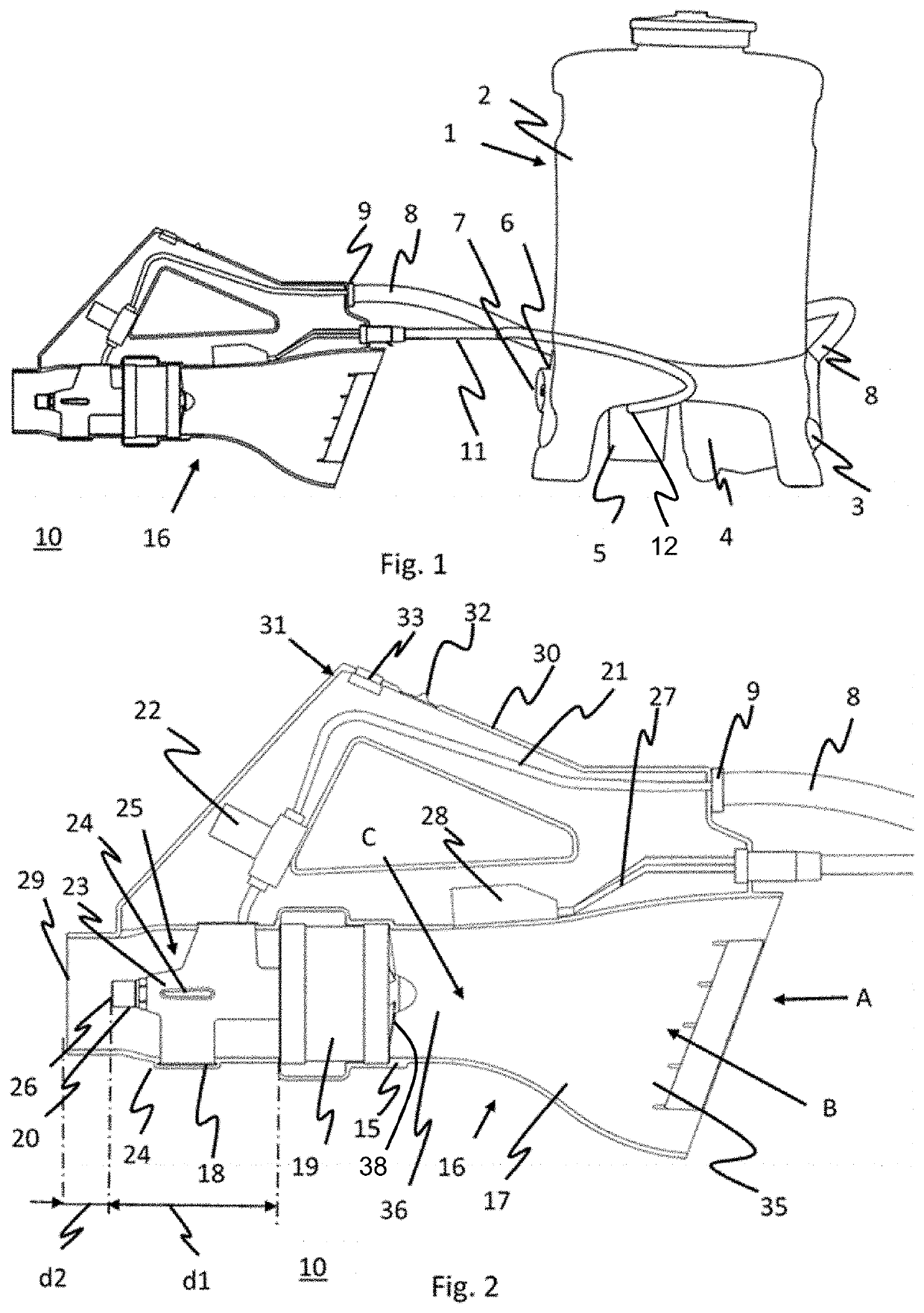
[0036]FIG. 1 shows a battery-operated back sprayer 1 from Birchmeier Sprühtechnik AG, CH-5608 Stetten, which is marketed under the name REC 15. This sprayer 1 has a liquid tank 2, an air tank 3, an electric pump 4 and a battery or accumulator 5. A pressure sensor 6 is provided on the air tank 3, which is attached to a pressure regulator 7 on the back sprayer 1. The pressure regulator 7 can be used to adjust the pressure to the spray liquid. In addition, a liquid supply line 8 is connected to the air tank 3, which is detachably attached to a portable blower spray device 10, according to a first example embodiment, with a connection 9. Furthermore, the blower spray device 10 is connected to the battery 5 by an electrical cable 11 with an electrical plug 12.

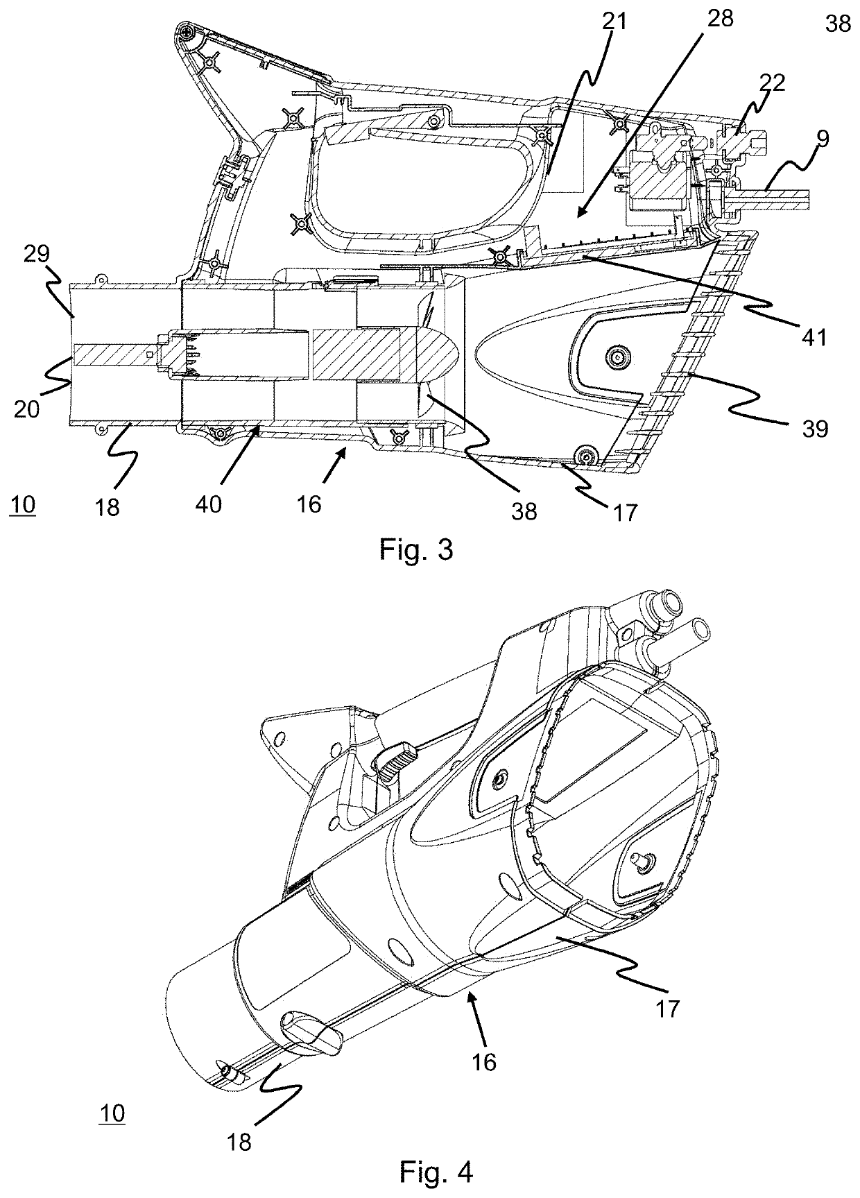
[0037]FIG. 2 shows an enlarged view of the blower spray device 10, with the front half of the housing removed so that only the rear housing half 15 of the housing 16 is visible. The housing 16 has a funnel-shaped intake channel 17 a...


PUM


Abstract

A blower spray device is provided having a housing which comprises an electrically driven blower and a spray nozzle, and having a liquid supply line opening into the spray nozzle. The housing has a funnel-shaped intake channel and a tubular blow-out channel, and an electrical valve is provided in the liquid supply line to activate and deactivate the liquid supply to the spray nozzle. An electronic controller having a regulating unit for the electric blower is further provided to adjust the air flow velocity.

Description

BACKGROUNDTechnical Field[0001]The disclosure relates to a blower spray device and a method for producing a spray mist with such a blower spray device.Description of the Related Art[0002]Blower spray devices, known as motor sprayers, are used, for example, for plant protection in agriculture or for pest control in horticulture.[0003]Such a motor sprayer is essentially composed of a spray tank portable on the back, a petrol engine and a blower, and is known for example from CH-A-327 997. An air filter is connected upstream of the blower intake chamber and the blower pressure chamber is connected to a wide compressed-air hose and a narrower supply-air line. The other end of this line opens out just above the bottom of the spray agent tank so that the escaping compressed air agitates the spray liquid in the tank. The exhaust air leaves the container via an exhaust air channel. An atomizer nozzle is provided at the outlet end of the compressed-air hose, to which a supply line for the sp...

Claims


Application Information

Patent Timeline
20 Feb 2020
Publication
US20200054000A1
IPC
A01M7/00; B05B7/00; B05B12/00; B05B12/18; B05B13/00
CPC
B05B12/0026; B05B7/0075; A01M7/0046; B05B13/005; B05B12/18; B05B7/2475; A01M7/0035; A01M7/0021
Inventors
ZWAHLEN, JÜRG; ZAUGG, MICHAEL