Device for ventilating a patient and process for the operation of the device

a technology for ventilating devices and patients, which is applied in the field of ventilating devices for patients and the operation of the device, can solve the problems of increasing the construction volume, microorganisms or the like carried by the exhaled breathing gas, and not reaching the dry area in the interior of the patient module, so as to maintain the operability of the sensor mechanism and not affect the fluid conductivity of the devi

Active Publication Date: 2020-02-27
DRAGERWERK AG
View PDF0 Cites 6 Cited by
  • Summary
  • Abstract
  • Description
  • Claims
  • Application Information

AI Technical Summary

Benefits of technology

[0019]One advantage of the present invention is that, on the one hand, an area that is “wet” and possibly loaded with microorganisms because of exhaled breathing gas during the operation and, on the other hand, and a “dry” area separated in space therefrom are formed in the interior of the housing of the patient module because of the HME filter located therein. The HME filter absorbs the moisture carried along by the exhaled breathing gas and stores this moisture.
[0020]During exhalation, the moisture carried along by the exhaled breathing gas thus does not reach beyond the HME filter, i.e., not in an area downstream of the HME filter. Additional advantages are associated with the “dry” area advantageously created in this manner in the interior of the housing of the patient module. These advantages pertain to the valve section and to a sensor mechanism or sensor arrangement comprised by the patient module or associated with the patient module.
[0021]The valve section comprised by the patient module is located in the dry area. Because of the valve section comprised by the patient module, the patient module is also a filter housing, which also comprises the actuator mechanism for controlling the inspiratory and expiratory breathing gas flows and which can be used close to the patient and is usually used close to the patient. The valve section comprises at least one exhalation valve, optionally at least one exhalation valve as well as at least one inhalation valve and a plurality of exhalation valves and at least one inhalation valve in case of a special embodiment. The valve or each valve comprised by the valve section is therefore likewise located in the dry area. This means that valve membranes or the like also remain dry and do not come into contact with the moisture carried long by the exhaled breathing gas. This maintains the operability of the valve or of each valve comprised by the valve section because wet valve membranes may, for example, stick or adhere to one another and thus may lead to different opening characteristics of a valve in comparison to a dry valve membrane.
[0022]A sensor mechanism of the patient module, for example, a pressure sensor or a plurality of pressure sensors, may also be located in the dry area of the housing of the patient module or be associated with this dry area.
[0023]Arrangement of the sensor mechanism in the dry area of the housing of the patient module avoids a contamination of the surface of the sensor mechanism and thus maintains the operability of the sensor mechanism. When the sensor mechanism is not located in the housing of the patient module, but is only associated with the dry a

Problems solved by technology

Thus, these microorganisms or the like also do not reach the dry area in the interior of the housing of the patient module.
In addition, any microorganisms or the like carried along by the exhaled breathing gas also do not reach the particle filter.
However, the use of the particle filter may also be associated with an increase in the construction

Method used


Image

  • Device for ventilating a patient and process for the operation of the device
  • Device for ventilating a patient and process for the operation of the device
  • Device for ventilating a patient and process for the operation of the device

Examples


Embodiment Construction

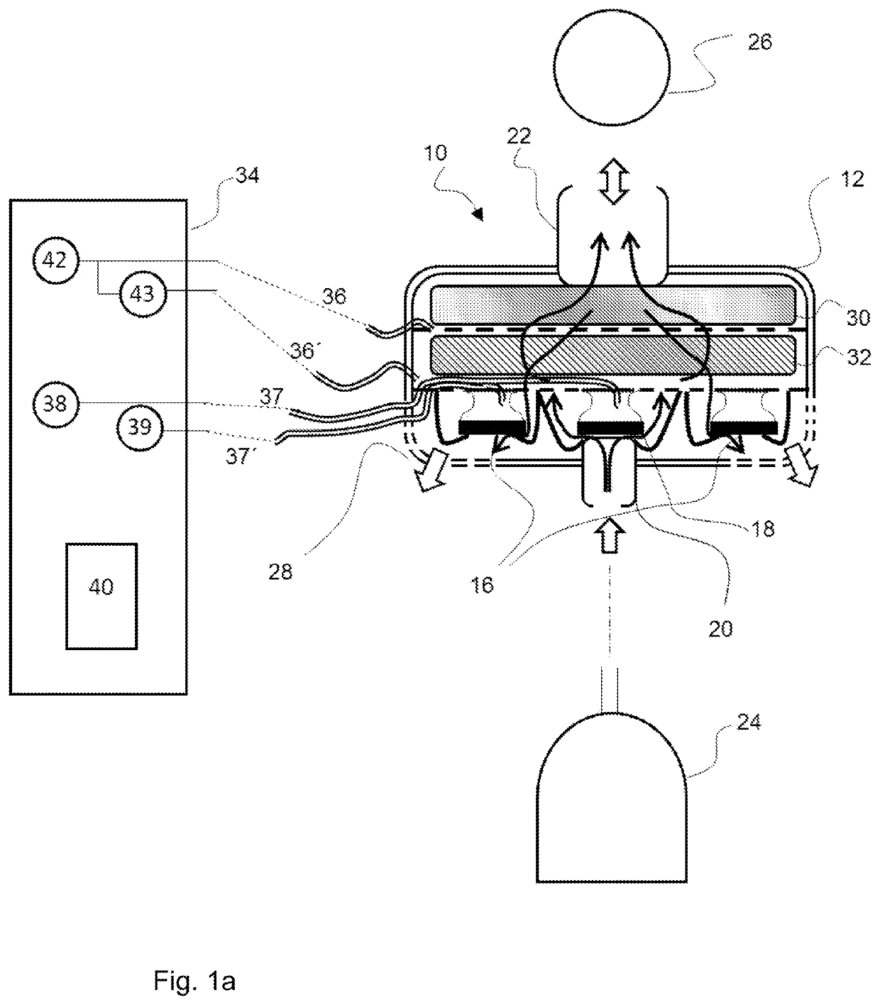
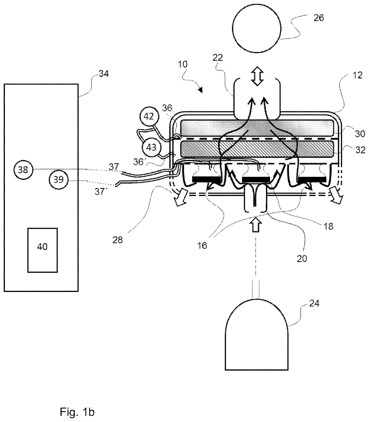
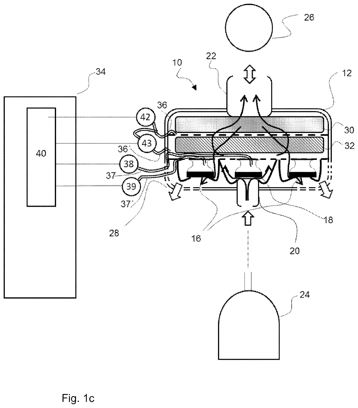
[0085]Referring to the drawings, the views in FIGS. 1a through 1e show individual embodiments of the device for ventilating a patient being proposed here as examples. Such a device is designated here and below as a patient module 10. The patient module 10 comprises a housing 12 and a valve section 14 (a section with at least one valve 16, 18) in the interior of the housing. The patient module 10 is shown in each case in a sectional view, so that the view of the interior of the housing 12 is free. The valve section 14 comprises at least one exhalation valve 16. In the embodiments being shown, the patient module 10 comprises two or more exhalation valves 16, and precisely two exhalation valves 16 can be seen in the viewing direction selected for the views in FIGS. 1a through 1e. In addition to the at least one exhalation valve 16, the patient module 10 comprises an (in principle, optional) inhalation valve 18 in the embodiments shown. The view of the valves 16, 18 is highly simplified...


PUM


Abstract

A patient module (10) is intended for use when ventilating a patient with a pressure source (24) that can be fluidically coupled via the patient module (10) to a patient interface (26), which can be connected to the airways of a patient. The patient module (10) includes a housing (12) and a valve section (14) in the housing (12) as well as an HME filter (30) spaced apart from the valve section (14). The HME filter (30) is located upstream of the valve section (14) in relation to an expiratory volume flow, so that the HME filter (30) divides an interior of the housing (12) into a dry area and an area coming into contact with the moisture carried along by the exhaled breathing gas. The valve section (14) is located in the dry area. A process for operating the patient module (10) includes calibration steps.

Description

CROSS REFERENCE TO RELATED APPLICATIONS[0001]This application claims the benefit of priority under 35 U.S.C. § 119 of German Applications 10 2018 006 699.2, filed Aug. 24, 2018, and 10 2019 004 760.5, filed Jul. 10, 2019, the entire contents of each application are incorporated herein by reference.TECHNICAL FIELD[0002]The present invention pertains to a device for ventilating a patient, which is designated below as a patient module, and furthermore, it also pertains to a process for the operation of the patient module.TECHNICAL BACKGROUND[0003]Devices for ventilating a patient are, e.g., ventilators (also known as respirators) or anesthesia devices. Ventilators and anesthesia devices—designated below in summary as ventilators or simply as ventilator—are used to provide breathing air to patients, who either cannot breathe independently at all or need help with breathing.[0004]For this purpose, the patients wear a face mask, which covers the mouth and nose, or a tube, which is inserte...

Claims


Application Information

Patent Timeline
IPC IPC(8): A61M16/00A61M16/10
CPCA61M2016/0033A61M2016/0027A61M16/1065A61M16/024A61M16/1045A61M16/107A61M16/204A61M16/205A61M16/16A61M2205/70A61M16/106A61M2205/7545A61M16/085A61M2205/3331A61M2206/14A61M16/201A61M16/0858
Inventor HANSMANN, HANS-ULLRICHLÜDTKE, NANDOHILTAWSKY, KARSTEN
Owner DRAGERWERK AG
Why Eureka
Try Eureka