Supercharge Your Innovation With Domain-Expert AI Agents!

Branch circuit thermal monitoring system for continuous temperature monitoring by directly applied sensors

Active Publication Date: 2020-02-27
SIEMENS IND INC
View PDF14 Cites 0 Cited by
  • Summary
  • Abstract
  • Description
  • Claims
  • Application Information

AI Technical Summary

Benefits of technology

The present invention is related to an electrical power distribution system that can continuously monitor the temperature of connection points, such as joints and cables. The system uses a plurality of thermal modules which are each connected with a thermal sensor assembly to provide continuous monitoring of their corresponding connection points. The thermal sensor assembly is directly applied to the connection point, eliminating the need for additional mounting assembly. The system also includes an expandable module rack and a main controller to communicate with the thermal modules. The invention helps to prevent overheating of electrical connection elements, preventing dangerous situations. Additionally, the system is designed to not interfere with the function of the power distribution system and can be easily retrofitted to existing systems.

Problems solved by technology

Overheating of electrical connection elements in electrical power distribution systems can cause catastrophic dangerous situations.
Typically installing infra-red view port designed for an electrical distribution system is expensive.
Further the view ports are intended to allow the assessment of fixed points of interest and cannot be used to identify the conditions of elements which are not in the line of sight from the view port.
The fiber optic technology while easily installable to the interested junction is an expensive technology.
These sensors require battery for the operations which have a limited life time before needing replacement.
This also exposes the installer or commissioning agent to hazardous conditions potentially caused by arc flash events when accessing the power distribution system.
However, the surface acoustic wave technology is also expensive for installation to the end user.

Method used


Image

  • Branch circuit thermal monitoring system for continuous temperature monitoring by directly applied sensors
  • Branch circuit thermal monitoring system for continuous temperature monitoring by directly applied sensors
  • Branch circuit thermal monitoring system for continuous temperature monitoring by directly applied sensors

Examples


Embodiment Construction

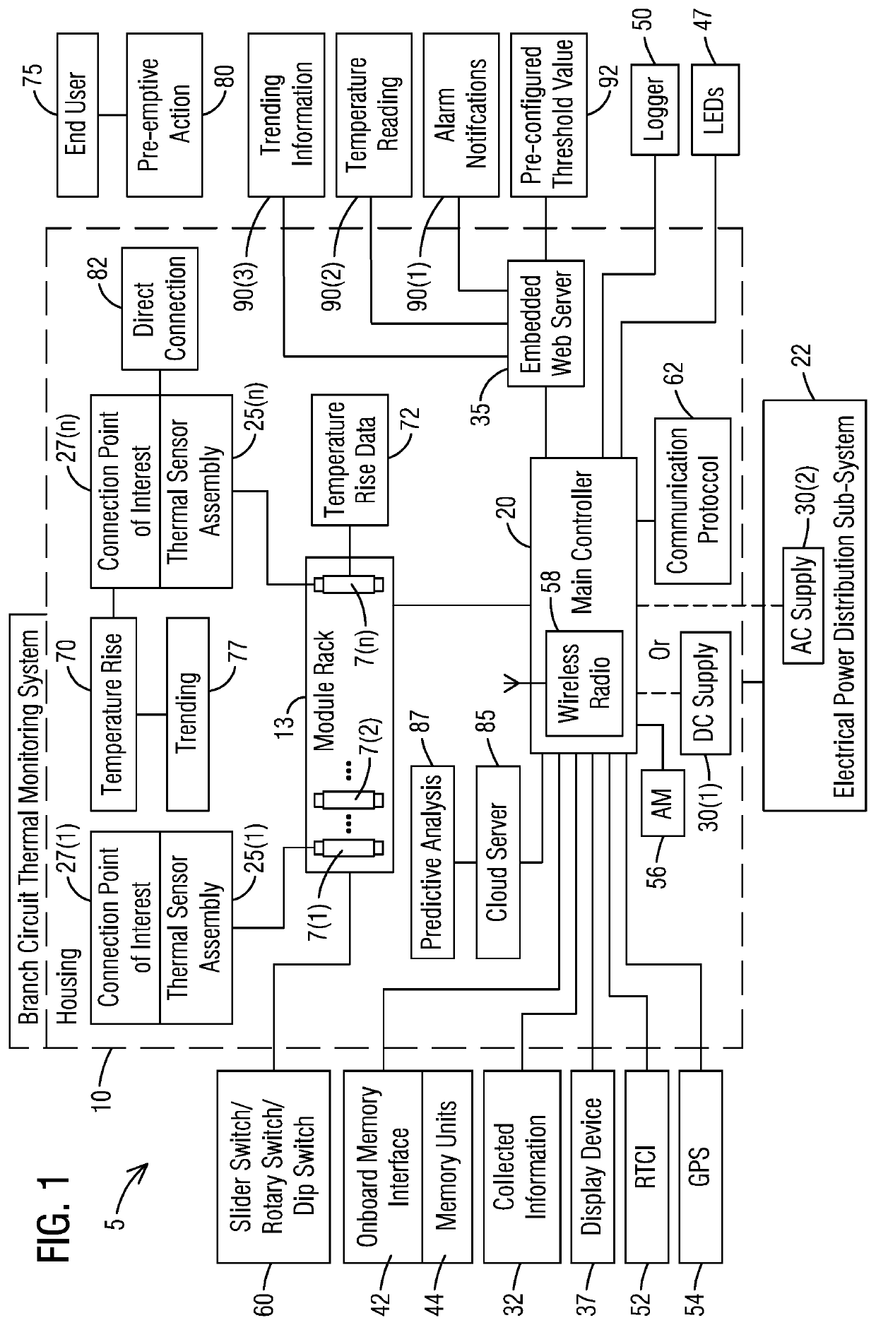
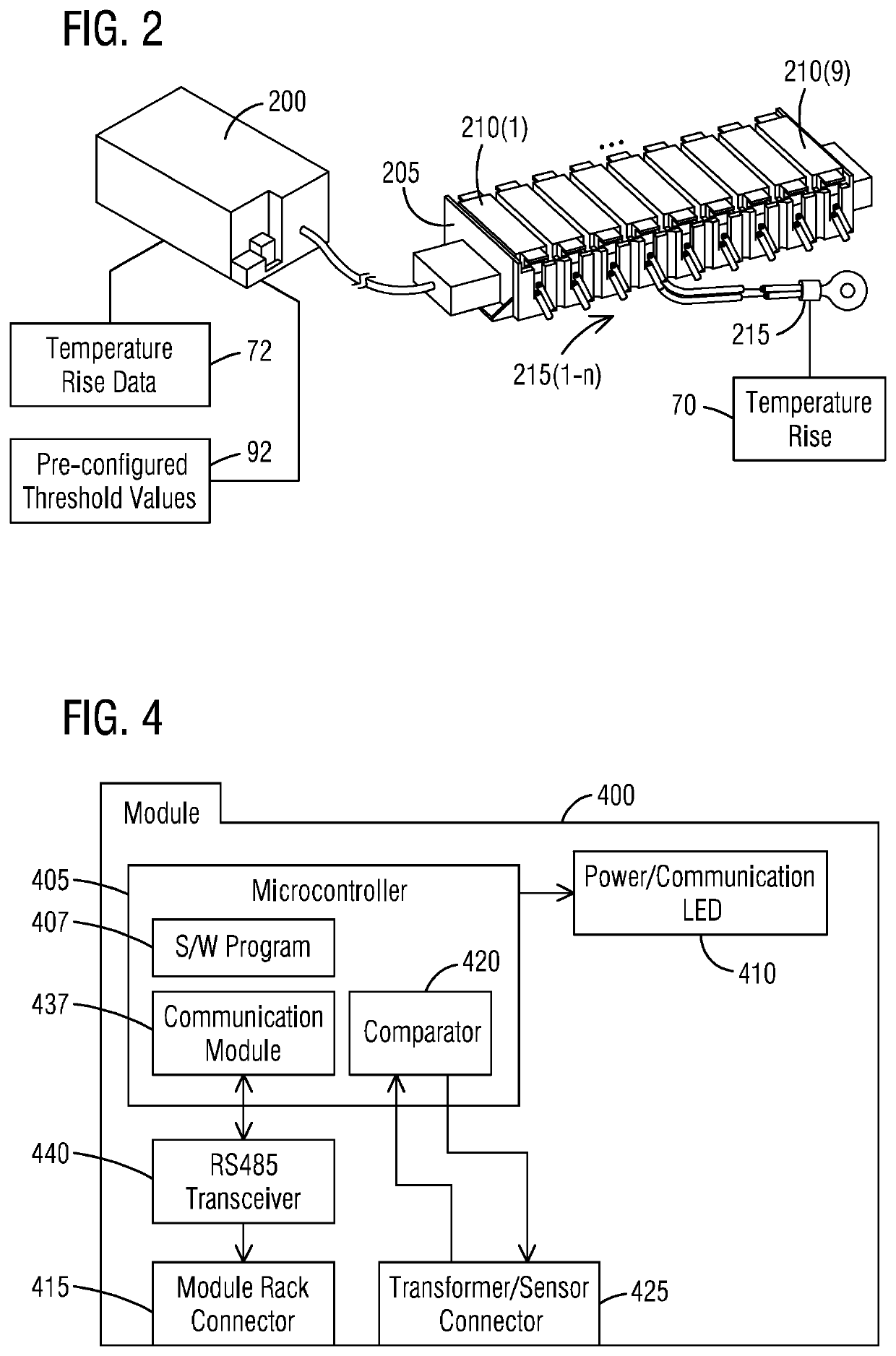
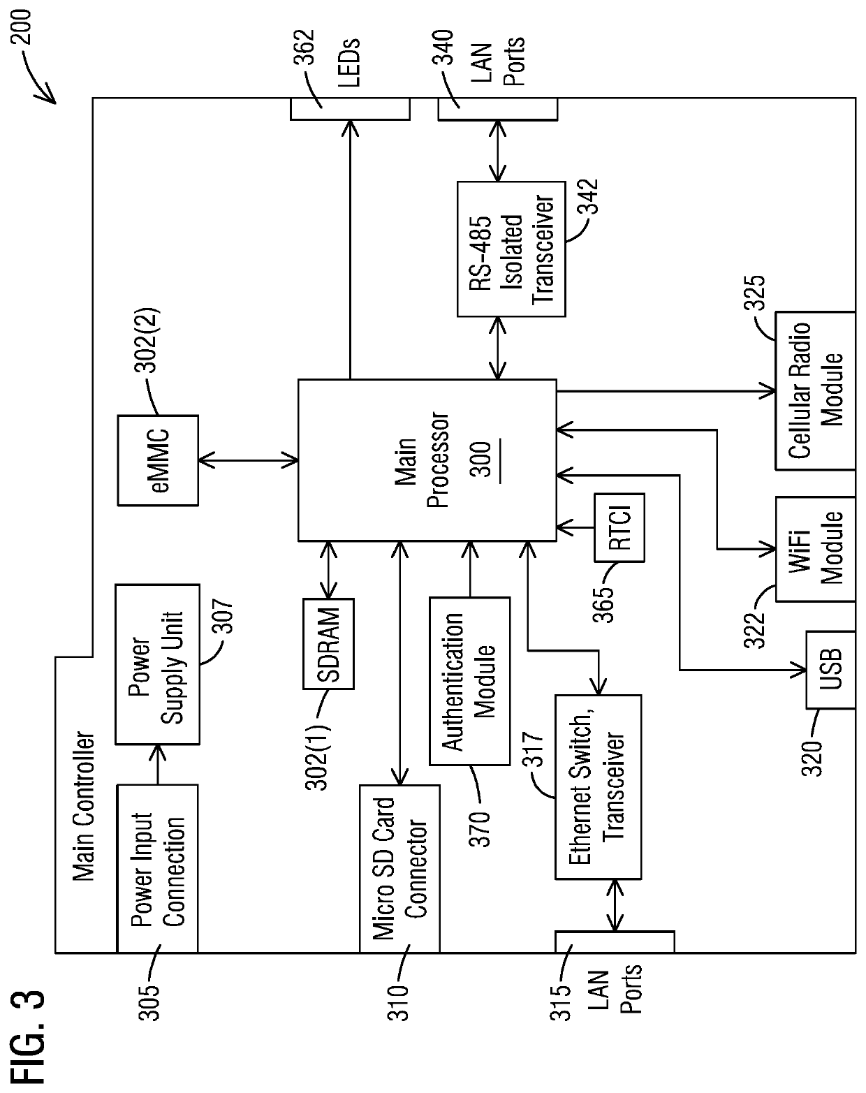
[0014]To facilitate an understanding of embodiments, principles, and features of the present invention, they are explained hereinafter with reference to implementation in illustrative embodiments. In particular, they are described in the context of a branch circuit thermal monitoring system for continuous temperature monitoring by directly applied sensors. The system may comprise module racks having different sensing mechanisms. The system may controllably manage placement and operation of thermal modules and thermal sensors which measure a temperature rise at one or more identified electrical connection points of interest in an electrical power distribution system. Embodiments of the present invention, however, are not limited to use in the described devices or methods.

[0015]The components and materials described hereinafter as making up the various embodiments are intended to be illustrative and not restrictive. Many suitable components and materials that would perform the same or...


PUM


Abstract

A branch circuit thermal monitoring system comprises a housing and an electrical power distribution sub-system. The housing includes a plurality of thermal modules each connected with a thermal sensor assembly of a plurality of thermal sensor assemblies. The housing further includes a module rack wherein each of the thermal modules is installed on the module rack. The housing further includes a main controller configured to communicate with the thermal modules. The thermal modules are configured for individually monitoring corresponding identified connection points of interest with the attached thermal sensor assemblies such that the thermal modules and the thermal sensor assemblies provide continuous temperature monitoring of the corresponding identified connection points of interest. The thermal sensor assembly is configured to be directly applied to a connection point of interest thus avoiding any additional mounting assembly. The electrical power distribution sub-system is coupled to the thermal modules.

Description

BACKGROUND1. Field[0001]Aspects of the present invention generally relate to a branch circuit thermal monitoring system for continuous temperature monitoring by modules with a thermal sensor assembly applied directly to a connection point of interest thus avoiding any additional mounting assembly.2. Description of the Related Art[0002]Overheating of electrical connection elements in electrical power distribution systems can cause catastrophic dangerous situations. To prevent such occurrences customers / end users of electrical power distribution system need to deploy monitoring of temperature rise in connection elements such as joints, lugs, cables in panel boards, switchboards, switchgear, bus way systems etc. Customers need to be notified within reasonable time of the rise in temperature with respect to any variations relative to established normal operating conditions.[0003]Typical thermal monitoring and measurement systems within electrical power distribution system are performed ...

Claims


Application Information

Patent Timeline
IPC IPC(8): G01K1/02G01K3/00
CPCG01K3/005G01K1/026G01K1/024G05B19/0423G01K7/00G05B2219/24215G01K1/02
Inventor NAYAK, AMITLEIDY, MATTHEW
Owner SIEMENS IND INC
Features
  • R&D
  • Intellectual Property
  • Life Sciences
  • Materials
  • Tech Scout
  • Unparalleled Data Quality
  • Higher Quality Content
  • 60% Fewer Hallucinations
Learn More