Scaling high-energy pulsed solid-state lasers to high average power

a laser and pulse technology, applied in laser details, laser optical devices, active medium materials, etc., can solve the problems of reducing laser efficiency, reducing laser pulse energy, so as to reduce amplifier gain, reduce laser pulse energy, and increase the power or energy of peek diode pump

Active Publication Date: 2020-03-05
LAWRENCE LIVERMORE NAT SECURITY LLC
View PDF0 Cites 0 Cited by
  • Summary
  • Abstract
  • Description
  • Claims
  • Application Information

AI Technical Summary

Benefits of technology

[0005]In high-energy (>10 J) pulsed solid-state lasers designed and built heretofore, all of which have used the single-pulse extraction (SPE) mode of operation, which is described below, efficient laser pumping requires pump-light pulses to be short compared with the fluorescence lifetime. Otherwise, fluorescence decay drains a significant fraction of the pumped ions bade to the ground state during the pump pulse. Impacts of fluorescence decay are reduced amplifier gain and reduced laser pulse energy. In some situations, however, in which it is necessary or desirable to produce a certain minimum amplifier gain or laser pulse energy, it is necessary or desirable to compensate for fluorescence decay by increasing peek diode pump-pulse power or energy. Either way, fluorescence decay reduces laser efficiency.
[0006]The cost of flash lamps or laser diodes scales with peak power. In turn, peak power scales inversely with the fluorescence lifetime. Therefore, to reduce system cost, it is desirable to use gain media with long fluorescence (storage) lifetime.
[0007]Efficient energy extraction requires that the cumulative fluence for the extracting beam be several times the saturation fluence. Cumulative fluence is the total fluence, found by summing the fluence over all passes the beam makes through amplifier. Cumulative fluence can be increased either by increasing the fluence per pass or by increasing the number of passes through the amplifier. The ability to increase fluence per pass is limited by optical damage risk. Specifically, to ensure reliable laser operation, the fluence per pass should remain well below the threshold for optical damage. On the other hand, the number of passes through the amplifier can also be limited. As a rule of thumb, it is relatively straightforward to achieve four or fewer passes through amplifiers, while it becomes more difficult to achieve more than four passes. For example, if multi-passing is achieved by using polarization rotation to switch the pulse into and out of the amplifier path, four or fewer passes can be achieved by using passive polarization-rotating components such as Faraday rotators, quartz rotators and half-wave plates. However, to achieve more than four passes, an active polarization-rotating component, e.g., a Pockels cell, is required. Pockets cells can add undesirable complications due to absorption of laser light and subsequent heating, generation of temperature gradients and concomitant birefringence of the Pockels cell crystal, particularly at high repetition rates. For large aperture sizes, transparent Pockels cell electrodes are needed to produce spatially uniform voltages and switching efficiency. Unfortunately, it has turned out to be difficult to develop transparent electrodes with high laser damage thresholds. Given these constraints on fluence and number of passes, it has until now been best design practice for high-energy lasers to choose gain media with sufficiently low saturation fluence that efficient extraction can be achieved in four or fewer passes.
[0008]To achieve high overall laser efficiency, both high pumping efficiency and high...

Problems solved by technology

Impacts of fluorescence decay are reduced amplifier gain and reduced laser pulse energy.
Either way, fluorescence decay reduces laser efficiency.
The cost of flash lamps or laser diodes scales with peak power.
The ability to increase fluence per pass is limited by optical damage risk.
On the other hand, the number of passes through the amplifier can also be limited.
As a rule of thumb, it is relatively straightforward to achieve four or fewer passes through amplifiers, while it becomes more difficult to achieve more than four passes.
Pockets cells can add undesirable complications ...

Method used


Image

  • Scaling high-energy pulsed solid-state lasers to high average power
  • Scaling high-energy pulsed solid-state lasers to high average power
  • Scaling high-energy pulsed solid-state lasers to high average power

Examples


Embodiment Construction

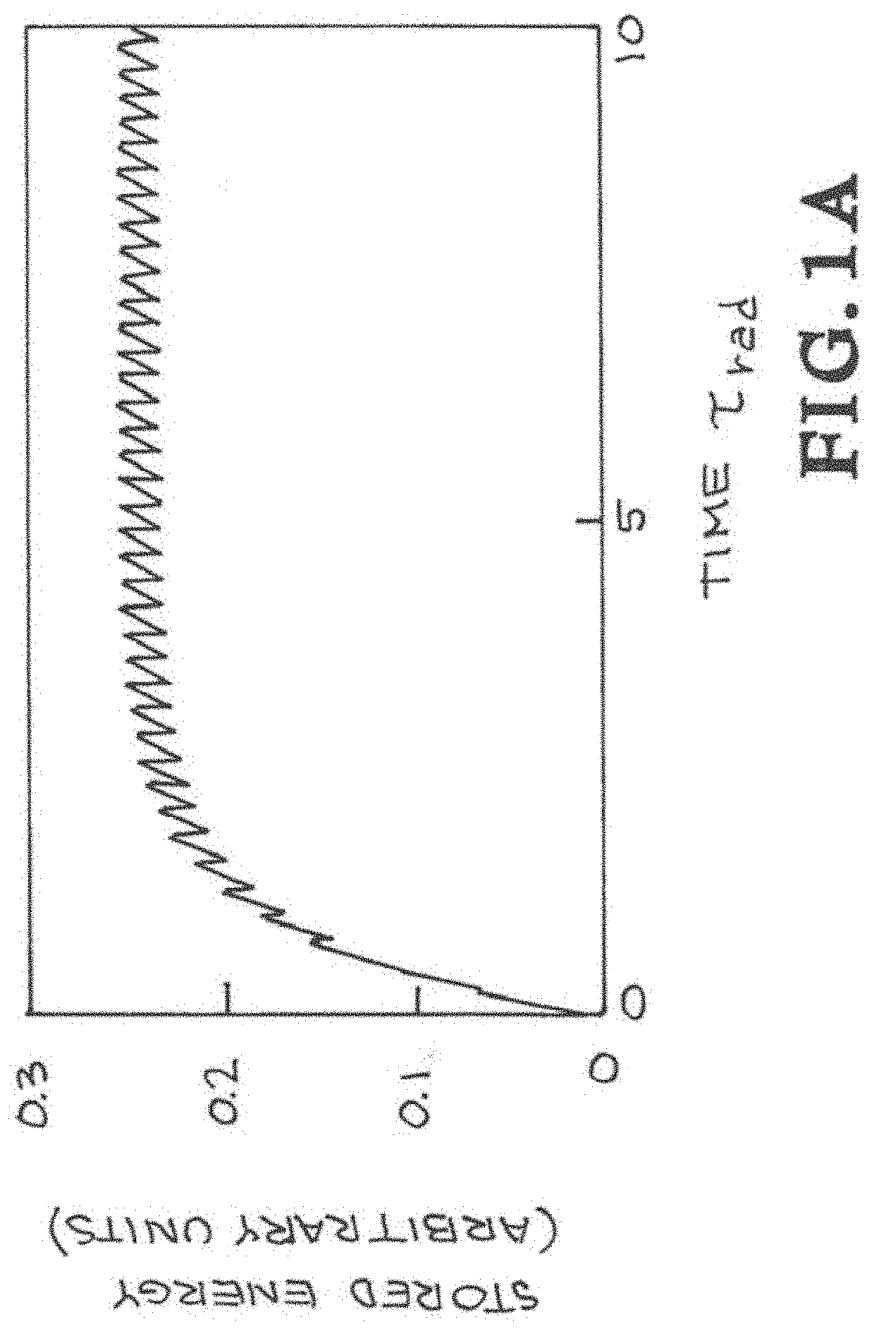
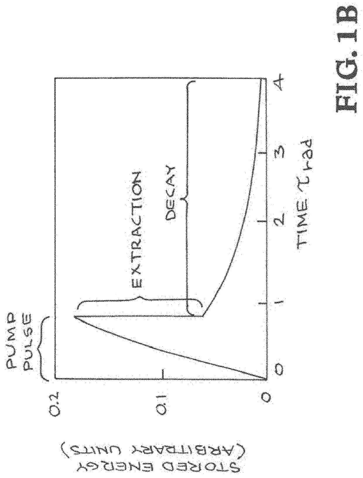
[0038]The present invention provides a method of multi-pulse extraction (MPE) for scaling up the average power of high-energy solid-state lasers while maintaining high efficiency. MPE can be applied when the pulse repetition rate, PRF, is approximately equal to or greater than the inverse of the storage lifetime, τstorage, i.e., when PRF * τstorage≥1. With MPE, pumping is continuous and only a small fraction of the energy stored in the amplifier is extracted by any one seed pulse. MPE stands in contrast with single-pulse extraction (SPE), in which a pump pulse of finite duration precedes each extracting pulse, FIG. 1 illustrates key differences between these two modes of operation.

[0039]FIG. 1A shows stored energy vs. time for the multi-pulse extraction (MPE) mode of operation. FIG. 1B shows stored energy vs. time for the single-pulse extraction (SPE) mode of operation. Time is normalized with respect to the radiative lifetime of the gain medium so that results are valid for gain me...


PUM


Abstract

Techniques are provided for scaling the average power of high-energy solid-state lasers to high values of average output power while maintaining high efficiency. An exemplary technique combines a gas-cooled-slab amplifier architecture with a pattern of amplifier pumping and extraction in which pumping is continuous and in which only a small fraction of the energy stored in the amplifier is extracted on any one pulse. Efficient operation is achieved by propagating many pulses through the amplifier during each period equal to the fluorescence decay time of the gain medium, so that the preponderance of the energy cycled through the upper laser level decays through extraction by the amplified pulses rather than through fluorescence decay.

Description

CROSS-REFERENCE TO RELATED APPLICATIONS[0001]This application is a continuation-in-part of International Application No. PCT / US2018 / 031435 titled “Scaling High-Energy Pulsed Solid-State Lasers to High Average Power,” filed May 7, 2018, incorporated herein by reference which claims the benefit of U.S. Patent Application No. 62 / 503,265 titled “A Method of Scaling High-Energy Pulsed Solid-State leasers to High Average Power,” filed May 8, 2017, incorporated herein by reference.STATEMENT REGARDING FEDERALLY SPONSORED RESEARCH OR DEVELOPMENT[0002]The United States Government has rights in this invention pursuant to Contract No. DE-AC52-07NA27344 between the U.S. Department of Energy and Lawrence Livermore National Security, LLC, for the operation of Lawrence Livermore National Laboratory.BACKGROUND OF THE INVENTIONField of the Invention[0003]The present invention relate to high-energy pulsed solid-state lasers, and more specifically, it relates to methods for scaling such lasers to high ...

Claims


Application Information

Patent Timeline
IPC IPC(8): H01S3/042H01S3/22H01S3/091
CPCH01S3/091H01S3/025H01S3/042H01S3/22H01S3/09415H01S3/1616H01S3/2316H01S3/2333H01S3/005H01S3/0057H01S3/0071H01S3/0404H01S3/0606H01S3/1653H01S3/0941H01S3/1001H01S3/10013H01S3/2341
Inventor ERLANDSON, ALVIN C.BAYRAMIAN, ANDREW J.HAEFNER, CONSTANTIN L.SIDERS, CRAIG W.GALVIN, THOMAS C.SPINKA, THOMAS M.
Owner LAWRENCE LIVERMORE NAT SECURITY LLC
Why Eureka
Try Eureka