
Wildlife Decoy With Flapper Apparatus

a technology of flapper and decoy, which is applied in the field of waterfowl decoys, can solve the problems of poor battery life, heavy spinning wing decoy, lack of motion of traditional style static waterfowl hunting decoy, etc., and achieve the effect of improving battery life and quiet operation

Active Publication Date: 2020-03-12
JARBOE NATHAN
View PDF0 Cites 2 Cited by
  • Summary
  • Abstract
  • Description
  • Claims
  • Application Information

AI Technical Summary

Benefits of technology

This patent describes a new technology that uses electromagnetism to create motion without traditional moving parts like bearings and electric motors. The technology uses a coil and a magnet to produce lifelike motion, with the resonant frequency of the spring / mass / magnet combination being the key factor. This technology has advantages of being simple, quiet, and efficient, and is ideal for use in waterfowl decoys with side-to-side tail motion. The unique design eliminates sliding and rolling parts, reducing noise and improving system reliability and efficiency.

Problems solved by technology

One of the major problems experienced by water fowl hunters is the lack of motion from traditional style static waterfowl hunting decoys.
However, many waterfowl have learned to identify spinning wing decoys and have learned not to venture near them, especially while the wings are spinning, seemingly because “spinners” are not realistic when viewed at close range.
Also, compared to traditional static decoys, these spinning wing decoys tend to be heavy, expensive, and require remote controls in order to turn on and off their motion at appropriate times to successfully lure waterfowl.
Electric motors and multiple moving parts have disadvantages including poor battery life, noisy operation, and poor performance as the batteries discharge and become unable to move the more bulky linkages.

Method used


Image

  • Wildlife Decoy With Flapper Apparatus
  • Wildlife Decoy With Flapper Apparatus
  • Wildlife Decoy With Flapper Apparatus

Examples


Embodiment Construction

[0030]The following description of exemplary embodiments is not to be taken as limiting but is for illustrating how the invention works in its elementary form. The scope of the invention is defined by the claims.

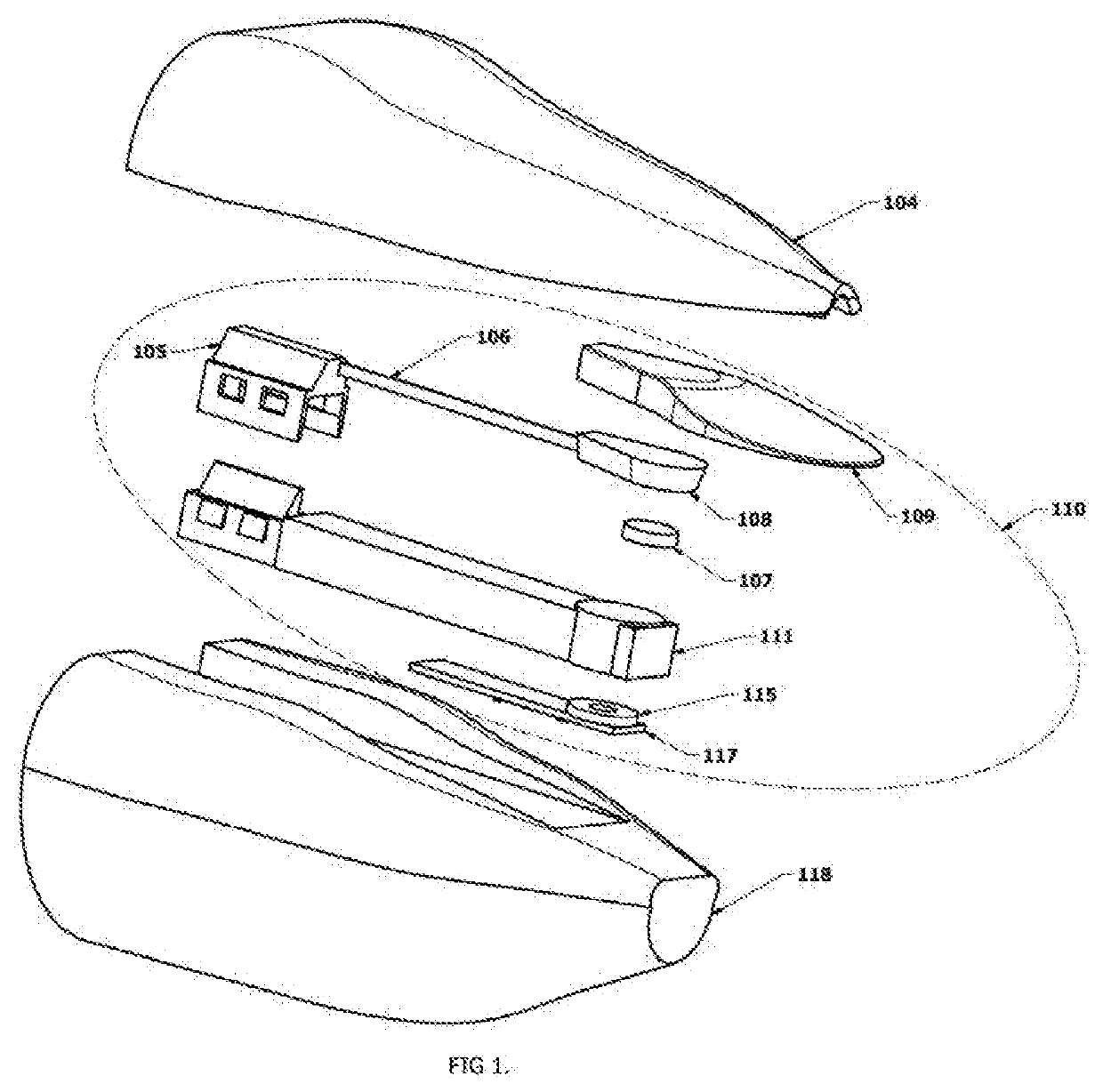
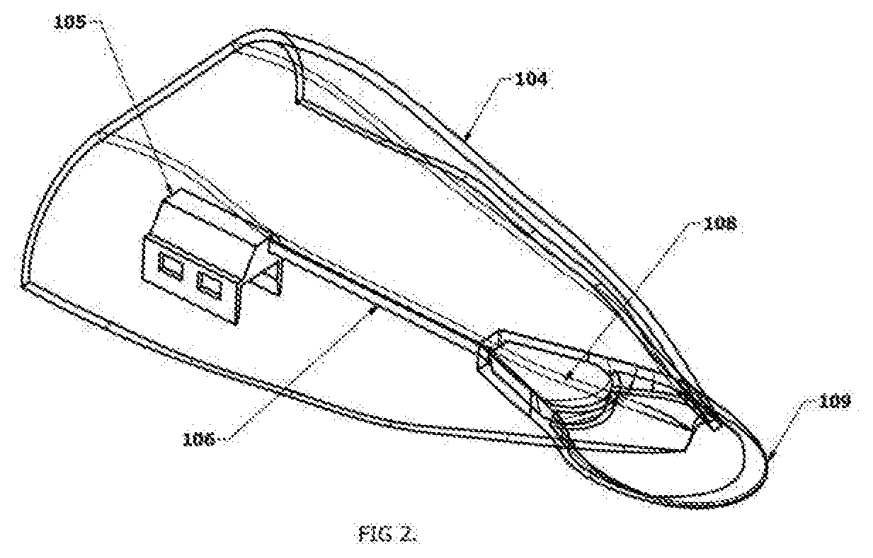
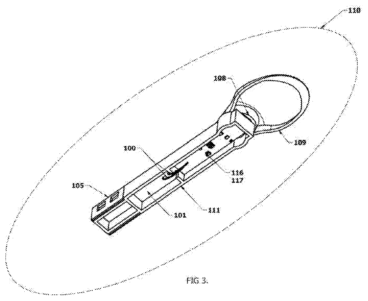
[0031]One main advantage of the invention is that it produces tail 109 motions with significantly less electrical power than competing products. Several competitors' decoys splash water, pump water, or spin plastic wings using traditional brushed electric motors through a pump or mechanical linkages and / or gears. The movement of air via wings which spin, or the movement of decoy appendages or movement of water requires much more power than the invention described here. Consequently, many prior decoys require much larger and more bulky batteries and motors to produce the desired motion. The side to side motion of the relatively light and flat tail 109 in the described invention creates little aerodynamic drag, and oscillates at the system resonant frequency, and is consequent...


PUM


Abstract

A mechanism for producing simulated tail motion or other motion in a waterfowl decoy. It may include a cantilevered carbon fiber composite spring clamped rigidly at one end and free at the other. At the free distal end of the spring, a permanent magnet and simulated tail are affixed. Fixed rigidly nearby, within the decoy body, near the magnet but not in direct contact with the magnet, is an inductor / coil. The coil is energized and de-energized at a frequency matching the resonant frequency of the spring / magnet / tail assembly, which causes the tail / magnet assembly to oscillate back and forth from side to side as the magnetic field within the coil varies, providing variable attraction between coil and magnet. Custom circuitry, which is energized by a battery, provides appropriately timed electrical impulses to the coil.

Description

CROSS REFERENCE TO RELATED APPLICATIONS[0001]This application claims priority to U.S. provisional patent application Ser. No. 62,727,788 filed on Sep. 6, 2018, which is hereby incorporated herein by reference in its entirety.FIELD[0002]The present invention relates generally to waterfowl decoys used for hunting and, more particularly, to waterfowl decoys that mimic real movements on the water. The technology may also be used to produce movement of other decoy appendages or features.BRIEF DESCRIPTION OF PRIOR ART[0003]Modern waterfowl hunting success requires luring waterfowl within relatively close range in order to harvest them with legal weapons such as shotguns. One common method to achieve this is to attempt to fool waterfowl into landing within close range by placing artificial birds—decoys—in the water or on land where the hunter desires the game to congregate in order to harvest them.[0004]One of the major problems experienced by water fowl hunters is the lack of motion from ...

Claims


Application Information

Patent Timeline
Patent Type & Authority Applications(United States)
IPC IPC(8): A01M31/06
CPCA01M31/06
Inventor JARBOE, NATHAN
Owner JARBOE NATHAN
Learn More