Device and method for tomographically visualizing viscoelasticity of tissue

a tomographic and viscoelasticity technology, applied in the field of tomographically visualizing the viscoelasticity of tissue, can solve problems such as affecting the practical use of the system

Pending Publication Date: 2020-03-12
MEIJO UNIVERSITY
View PDF4 Cites 5 Cited by
  • Summary
  • Abstract
  • Description
  • Claims
  • Application Information

AI Technical Summary

Benefits of technology

[0008]In view of the above and other circumstances, one of objects of the present invention is to provide a technology that enables mechanical characteristics evaluation through OCT measurement even on an object requiring strict quality assurance.

Problems solved by technology

In a case where an object, such as regenerated tissue, requiring strict quality assurance is to be measured, however, the contact of such a piezoelectric device may cause tissue contamination, which may hinder practical use of the system.

Method used


Image

  • Device and method for tomographically visualizing viscoelasticity of tissue
  • Device and method for tomographically visualizing viscoelasticity of tissue
  • Device and method for tomographically visualizing viscoelasticity of tissue

Examples


example

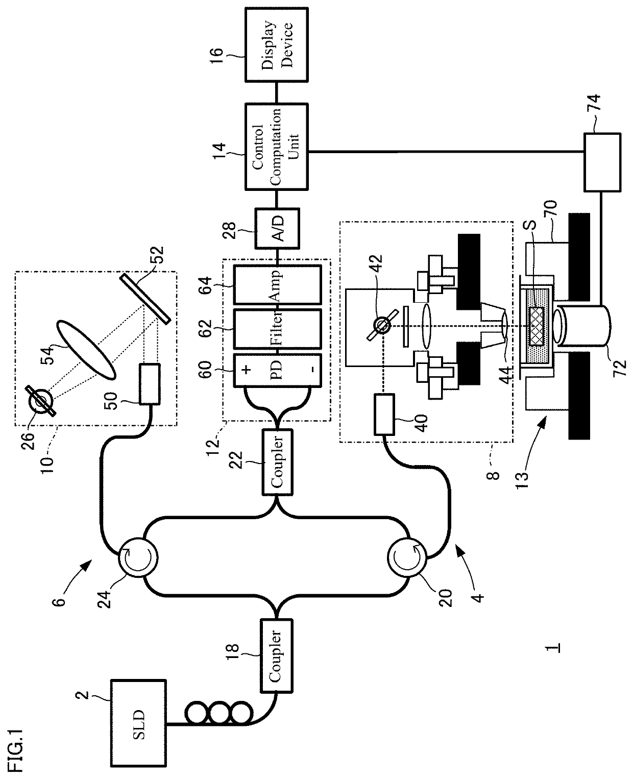
[0036]FIG. 1 is a diagram schematically illustrating a configuration of a viscoelasticity visualizing device according to the example. The device according to the example tomographically measures the viscoelasticity of regenerated tissue in microscale to visualize the viscoelasticity. For the tomographic measurement, load application by acoustic radiation pressure and detection by the OCT are used.

[0037]As illustrated in FIG. 1, an OCT device 1 includes a light source 2, an object arm 4, a reference arm 6, optical mechanisms 8 and 10, an optical detector 12, a loading device 13, a control computation unit 14, and a display device 16. The respective optical components are connected with one another by optical fibers. While an optical system based on a Mach-Zehnder interferometer is presented in the example illustrated in FIG. 1, other optical systems such as a Michelson interferometer may alternatively be used. In addition, while time domain OCT (TD-OCT) is used as the OCT in the pre...


PUM

PropertyMeasurementUnit
viscoelasticityaaaaaaaaaa
optical coherence tomographyaaaaaaaaaa
deformation energyaaaaaaaaaa

Abstract

A device according to an embodiment includes an optical system employing the OCT, and tomographically visualizes the viscoelasticity of tissue of an object. The device includes an optical mechanism that guides light from a light source to the tissue of the object to scan the tissue, a loading device that applies deformation energy to the tissue, a control computation unit that computes tomographic distribution of the viscoelasticity of the tissue by controlling driving of the loading device and the optical mechanism and processing an optical interference signal from the optical system on the basis of the driving, and a display device that displays the viscoelasticity of the tissue in a form of tomographic visualization. The loading device is a non-contact loading device that loads acoustic radiation pressure in the tissue by outputting ultrasonic waves toward a focus point set in the object.

Description

CROSS-REFERENCE TO RELATED APPLICATIONS[0001]This application is a continuation application of International Application No. PCT / JP2018 / 018455, filed on May 14, 2018, which claims priority to and the benefit of Japanese Patent Application No. 2017-096134, filed on May 15, 2017. The contents of these applications are incorporated herein by reference in their entirety.BACKGROUND OF INVENTION1. Field[0002]The present invention relates to a device and a method capable of tomographically displaying in microscale the viscoelasticity of tissue of an object to be measured.2. Description of Related Art[0003]In recent years, for further development of medical diagnostic technology, clinical applications of optical coherence tomography (hereinafter referred to as “OCT”) are underway. The OCT is tomography using low-coherence optical interference, which enables visualization of distribution of biological tissue forms at high spatial resolution in microscale. In addition, the acquisition rate in...

Claims


Application Information

Patent Timeline
Patent Type & Authority Applications(United States)
IPC IPC(8): A61B5/00G01B9/02G01N29/06
CPCG01N29/0672A61B5/442A61B5/004A61B5/0066G01B9/02091A61B1/00A61B8/08G01N21/17G01B11/161G01N2291/02827G01N2291/02818G01N29/2418
Inventor SAEKI, SOUICHI
Owner MEIJO UNIVERSITY
Why Eureka
Try Eureka