Conduit and component support system

a support system and conduit technology, applied in the direction of pipe supports, sheet joining, electrical equipment, etc., can solve the problems of air gap affecting the operation of the conduit, not fully revealing its features, etc., and achieve the effect of dampening the sound of the condition, building tolerances for outside forces, and reducing the effect of hydraulic shock if not suppressed or managed within the condui

Inactive Publication Date: 2020-03-12
PERRY SHAWN FREDERICK DOUGLAS
View PDF0 Cites 8 Cited by
  • Summary
  • Abstract
  • Description
  • Claims
  • Application Information

AI Technical Summary

Benefits of technology

[0007]Still another advantage of the invention is the physical protection engineering as part of the device. Many conduits are either installed outside a building structure where they travel to concrete pads or other structures beside or outside of the main building structure, on roof tops, beside or at machinery, inside or outside areas where workers must travel to complete inspections, work on or above conduits leaving conduits unprotected from physical damages. Prior art Jentzsch U.S. Pat. No. 3,888,186; Valeri U.S. Pat. No. 4,067,258 Martin U.S. Pat. No. 5,095,822; Herman U.S. Pat. No. 5,777,266; Berardi U.S. Pat. No. 6,499,410; Henry U.S. Pat. No. 6,878,811; Lubanski U.S. Pat. No. 7,309,836; Henry U.S. Pat. No. 7,939,759; Lubanski U.S. Pat. No. 8,119,914 and Lioi U.S. Pat. No. 9,438,022; describe and teach of protection methods in the forms of ramps for heavy equipment or foot traffic at special events. This invention as disclosed is not meant for protection of vehicular traffic but from physical damages to the conduits caused by workers standing on conduits to gain access to other equipment, falling objects from workers working above conduits, from processes of equipment or those from such physical damages that can occur from moving or falling ice and snow loads. The design of this invention has built in tolerances for outside forces such as impact from falling objects, foot traffic and similar forces imposed on conduits while providing inspection access without dismantling the protection device also providing identification to conduits. Furthermore, this invention will allow for simple attachment where conduits are installed within or around pipe racking. Many conduits require work to be completed within such pipe racking where workers have to build on site wooded structures or similar. The invention as described and illustrated in the drawing figures now solves physical protection of a conduit relative to size wherein now protection can be accomplished within or around equipment, in pipe racking, on roof areas, between buildings or similar to those areas above.
[0008]Protection of a conduit is critical in the success of the functions in which a conduit performs and as such this invention through risk assessment provides not only protection as described above but allowance and compensation for conduit release from structural objects. Extreme movement or fatigue of a structural object to where a conduit is attached can cause extreme harm to a conduit support, a conduit and to the function a conduit performs; now as disclosed this invention can manage extreme conditions by allowing a conduit to be released prior to critical fatigue of the conduit.
[0009]Another advantage of the current invention is the support of semi rigid conduits where support is not only provided at strategically placed supports, but throughout the entire run of a conduit. Past practices have been the use of wooden planks placed beneath corrugated conduits for entire system support, this invention now solves entire system protection for semi rigid conduits as well.
[0010]Vibrations within conduit systems including those apparent in liquid system are accounted for and protected from within this said invention or device. Hydraulic shock is due to flow being suddenly stopped within a conduit and should be accounted for within the designs of conduit protection. Devices like shock absorbers and expansion tanks provide internal relief for hydraulic shock as shown by Tsai U.S. Pat. No. 9,004,110, however, this does not protect the outside of the conduit if such devices intended to absorb inner shock are not installed, or depleted, undersized or not installed in the correct location. These vibrations due to hydraulic shock can cause conduits to bang, m

Problems solved by technology

, and is not a comprehensive disclosure of all of its features.
This separation of conduits may also isolate conduits from o

Method used


Image

  • Conduit and component support system
  • Conduit and component support system
  • Conduit and component support system

Examples


Embodiment Construction

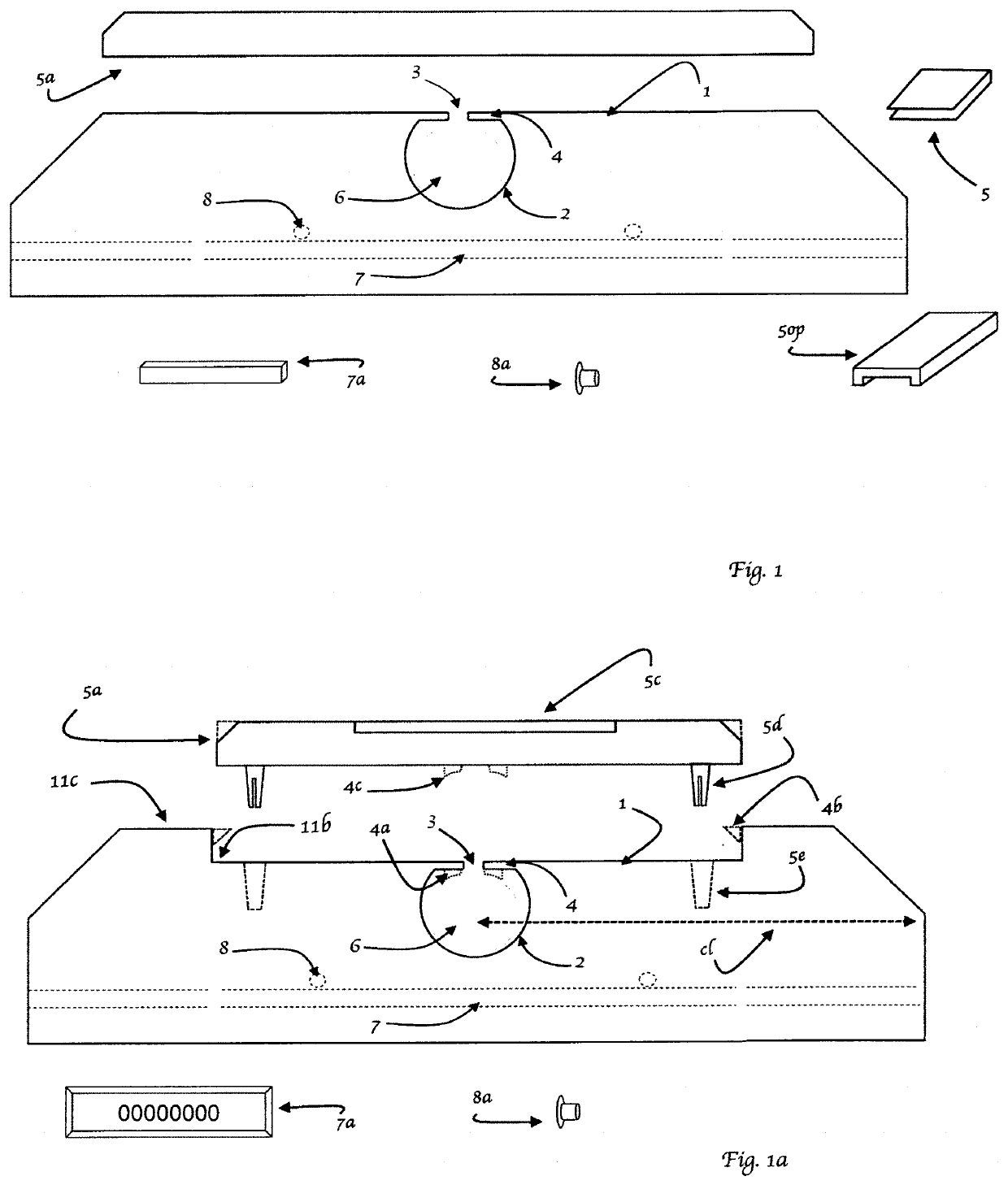
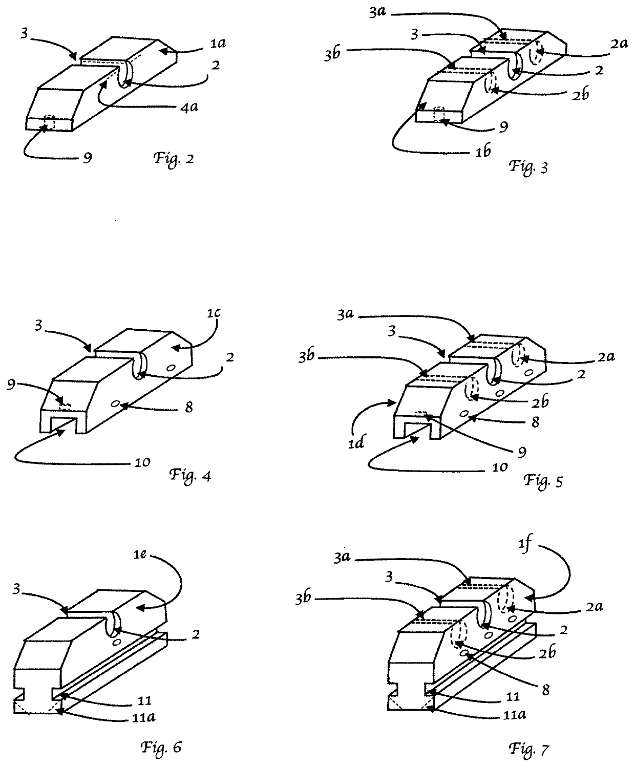
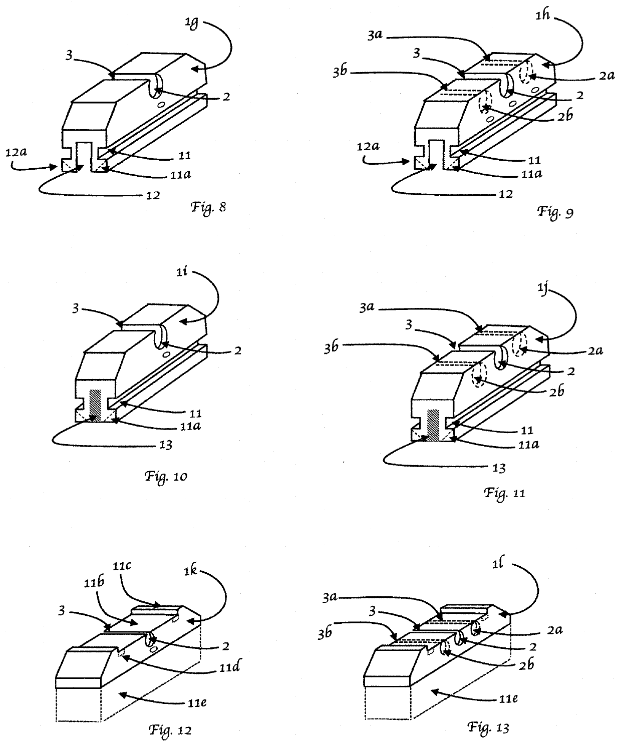
[0102]In the following description with the use of the figures or illustrations, numerical and or alphabetical references may refer to similar components and elements. The components, elements and or embodiments may also be identified numerically, alphabetically, or a combination of both described or configured to point to one element, component or embodiment; where this appears, the meaning may be for all that appear as illustrated and described where sense can be made. The embodiments, components, configurations and materials illustrated in the figures or described within this description are preferred embodiments only and are given solely for explanation purposes. Where similar depictions or drawings are made these similar descriptions where sense can be made are to be understood without duplication of such descriptions for each Illustration. Descriptions of well-known components are omitted so as to not unnecessarily obscure the principle features of the invention. It is noted t...


PUM


Abstract

A conduit and component support system for support of flexible, semi flexible or ridged conduit, pipe, wire, or similar, herein referred to as conduit which is comprised of one or more attachment points completing the underlying supporting framework for conduits. This system may be comprised of a nonmetallic elastomeric material or similar where a conduit can either be placed on the support or inserted into an insert opening within the support. This system provides support for conduit elongated runs and also to where the joining of conduits is made, where changes in direction are made, or where attachment points are made within a conduit system. Examples: 90 degree turns, tee fittings, couplings, valves, junction boxes, or similar to those previously mentioned. The system may also provide; physical protection, allowance for expansion and contraction, corrosion protection, dielectric protection, wear protection, identification, vibration and shock protection for conduits, the system, or structures.

Description

CROSS-REFERENCE TO RELATED APPLICATIONS[0001]This application claims priority to provisional U.S. Application No. 62 / 559,549 filed Sep. 16, 2017; U.S. Application No. 62 / 590,541 filed Oct. 25, 2017; and U.S. Application No. 62 / 655,813 filed Apr. 11, 2018.FIELD OF INVENTION[0002]The invention is a conduit support system for use in supporting or securing piping, conduits and electrical wiring found in plumbing waste, water and venting, heating and air conditioning, gas lines in liquid and vapor states, oil piping, pneumatic and hydraulic piping, fire protection systems, electrical conduits and wires or similar to any of the previous mentioned all herein referred to as conduits. The support system in some aspects will include the support of the fittings and components used within a conduit; such fittings and components included but are not limited to 90 degree elbows, 45 degree elbows, T fittings, couplings, flanges, unions, valves, regulators, junction boxes, disconnects, meters, or a...

Claims


Application Information

Patent Timeline
IPC IPC(8): F16L3/24F16L3/133F16L3/18H02G3/32
CPCF16L3/18H02G3/32F16L3/24F16L3/133F16B5/12F16L3/1091F16L3/13F16L3/223F16L3/243F16L57/00H02G3/0456
Inventor PERRY, SHAWN FREDERICK DOUGLAS
Owner PERRY SHAWN FREDERICK DOUGLAS
Why Eureka
Try Eureka