Inductive component

a technology of inductive components and components, applied in the direction of printed circuit aspects, printed inductances, printed inductances, etc., can solve the problem of complex manufacturing methods

Active Publication Date: 2020-03-12
KASCHKE COMPONENTS GMBH
View PDF0 Cites 0 Cited by
  • Summary
  • Abstract
  • Description
  • Claims
  • Application Information

AI Technical Summary

Benefits of technology

[0005]The object of the present invention is therefore to provide an

Problems solved by technology

In an arrangement of this kind, the problem is that the wires from which the conductor loops are formed have to first be twis

Method used


Image

  • Inductive component
  • Inductive component
  • Inductive component

Examples


Embodiment Construction

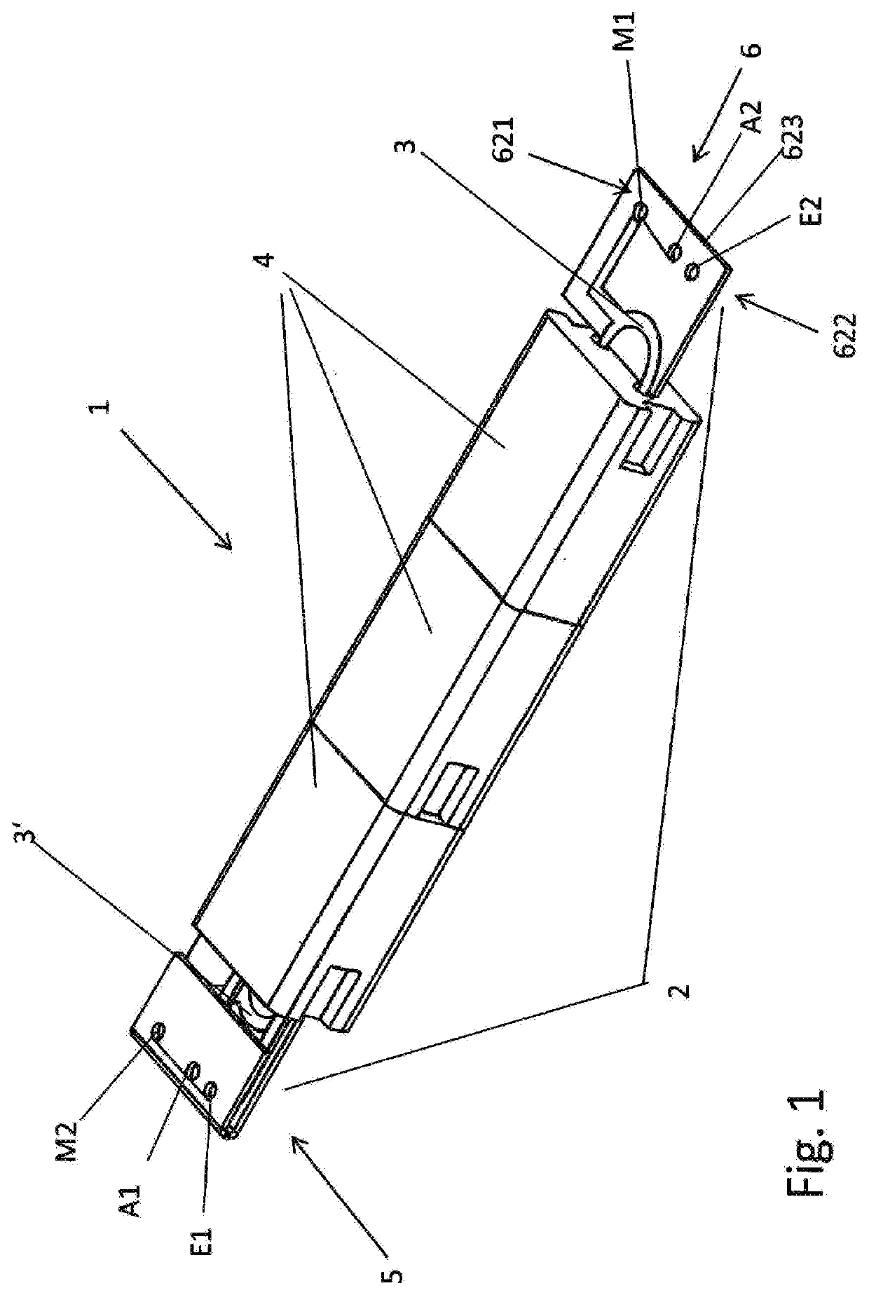
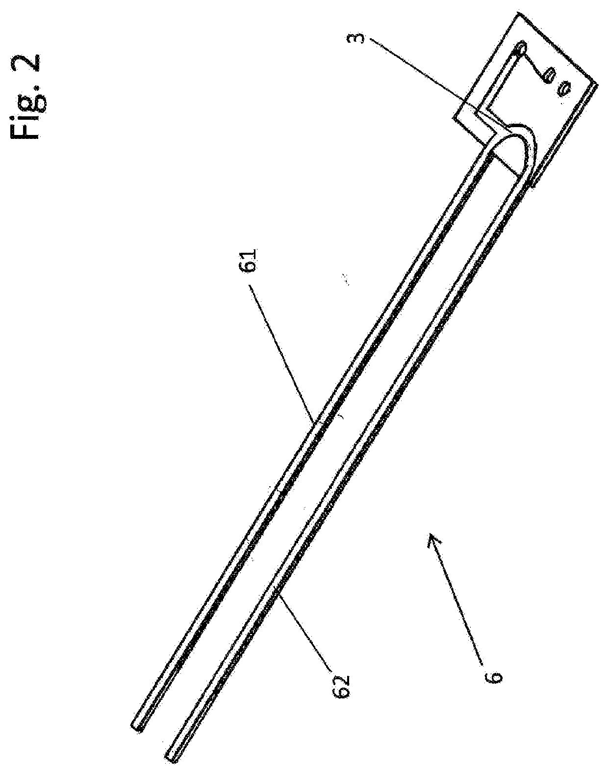
[0027]FIG. 1 is a perspective view of an inductive component 1 according to the invention in a fully assembled state. In the example shown, the inductive component 1 has conductor loops 3, 3′ arranged on a printed circuit board 2. The printed circuit board 2 comprises an upper face 621, a lower face 622 and narrow faces 623 and two printed circuit board parts 5, 6, each of which has one part of the at least one conductor loop 3, 3′. In the embodiment shown, the printed circuit board part 6, as shown in FIG. 2, has two projections 61, 62.

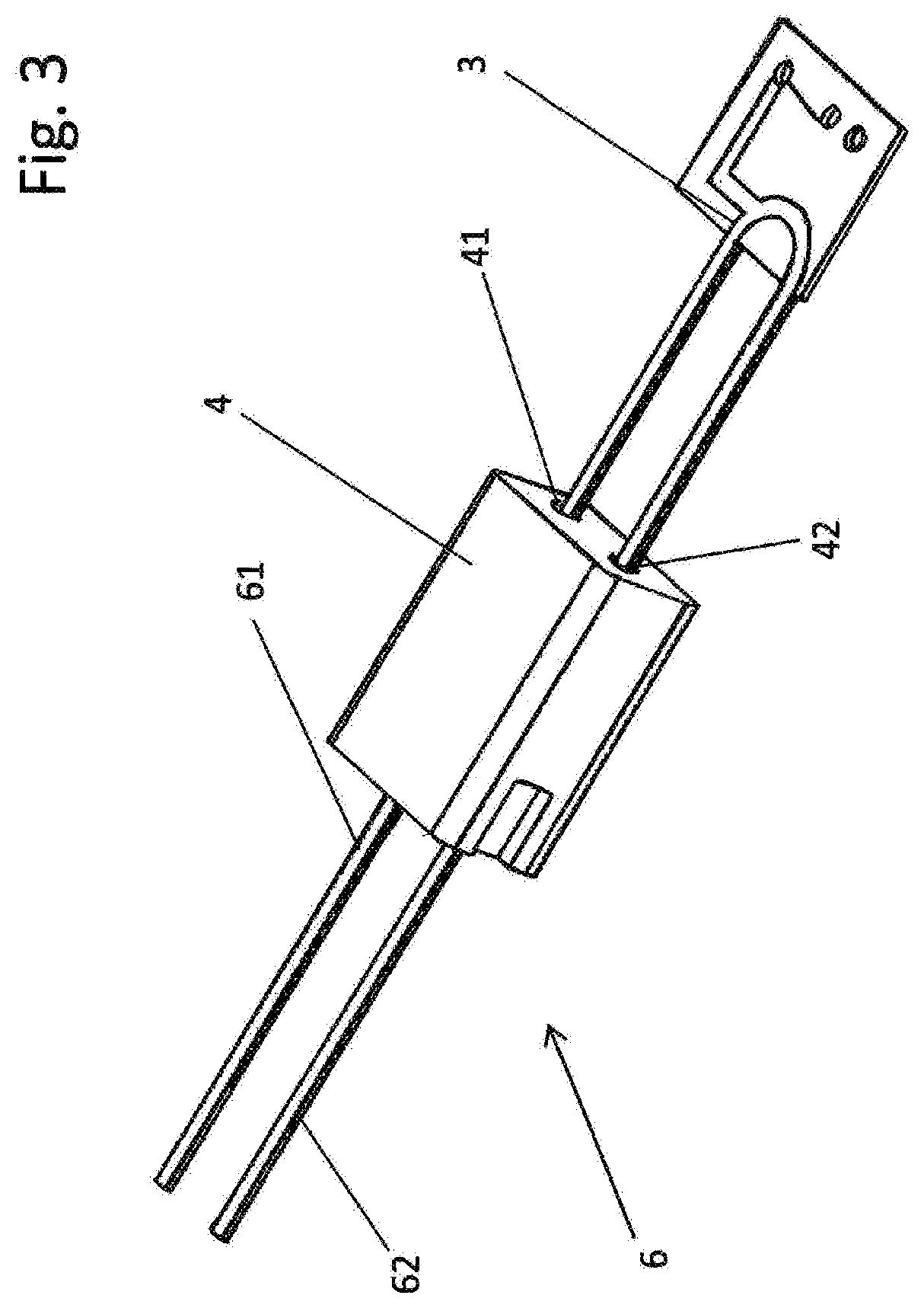
[0028]During assembly of the inductive component 1, as shown in FIG. 3, a core 4 made of inductive material, in which two holes 41, 42 are made, is pushed onto the projections 61, 62, In the embodiment of the inductive component 1 shown in FIG. 1, three cores 4 are pushed onto the projections 61, 62 by way of example. The inductive component 1 is completed by attaching the printed circuit board part 5. The assembly of the printed circuit board part 5...


PUM


Abstract

An inductive component has at least one conductor loop arranged on a printed circuit board and at least one core made of inductive material that cooperates inductively with the conductor loop. The printed circuit board comprises an upper face, a lower face and narrow faces, and moreover at least two printed circuit board parts. Each printed circuit board part has a part of the at least one conductor loop. At least one of the printed circuit board parts comprises a first and a second contact portion. The first contact portion is connected to a first face, in particular the upper face, of the second printed circuit board part and the second contact portion is connected to a second face, in particular the lower face, of the second printed circuit board part, which second face is different from the first face.

Description

CROSS REFERENCE TO RELATED APPLICATIONS[0001]This application is the US National Phase of and claims the benefit of and priority on International Application No. PCT / EP2018 / 050187 having an international filing date of 4 Jan. 2018, which claims priority on German Patent Application No. 10 2017 100 458.0 having a filing date of 11 Jan. 2017.BACKGROUND OF THE INVENTIONTechnical Field[0002]The invention relates to inductive components, as used in transmission devices for computer networks, for example.Prior Art[0003]In computer networks, inductive components in particular are used for galvanic isolation between the electric circuits, in order to be able to achieve high transmission rates between different terminals of a network installation that are in the range of a few gigabits per second and are as interference free as possible.[0004]Known components have two terminal faces, to each of which a conductor loop is coupled. The two conductor loops are each in the form of a wire, and are...

Claims


Application Information

Patent Timeline
IPC IPC(8): H01F17/00H05K1/03H05K1/02H01F27/29H01F27/26H01F27/30H05K1/16
CPCH01F2017/0073H01F2017/006H01F27/29H05K1/0278H05K1/0346H01F27/306H01F17/0006H05K1/165H01F27/266H05K2201/058H01F27/255H01F2027/2819
Inventor SCHWETJE, CARSTEN
Owner KASCHKE COMPONENTS GMBH
Why Eureka
Try Eureka