Position detection based on tissue discrimination

Active Publication Date: 2020-03-19
KONINKLJIJKE PHILIPS NV
View PDF0 Cites 0 Cited by
  • Summary
  • Abstract
  • Description
  • Claims
  • Application Information

AI Technical Summary

Benefits of technology

[0019]According to an embodiment, the system may further comprise an instrument for inserting the device into the region of interest, for example a bone, wherein a position and orientation of the instrument is traceable by a tracking device. A visualization may be generated including an indication of a relation of the instrument to the region of interest, without exposing the patient with x-ray radiation.
[0020]The systems according to the mentioned embodiments is ada

Problems solved by technology

In fact, pedicle screws are inserted either more or less blindly or under ofte

Method used


Image

  • Position detection based on tissue discrimination
  • Position detection based on tissue discrimination
  • Position detection based on tissue discrimination

Examples


Embodiment Construction

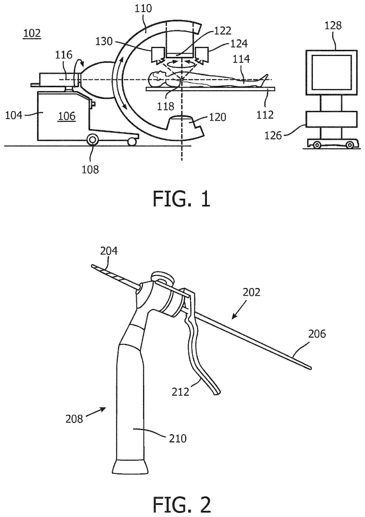
[0039]FIG. 1 is a schematically illustration of a system 102 comprising an X ray device 104 for providing X ray images of a patient's interior. The X ray device 104 has a base frame 106 supported by wheels 108, a movable C arm 110 and a patient's table 112 for supporting a patient 114. In this particular example, the patient 114 is a human being, but may also be an animal. The C arm 110 is rotatable with regard to a first axis 116, which axis has a direction corresponding to a main orientation of the surgical table 112, and to a second axis 118, which second axis is perpendicular to the first axis and parallel to the patient's table 112. An X ray source 120 and an X ray detector 122, which is preferably a rectangular and flat detector, are mounted on the C arm 110 such that the X ray source and the X ray detector reside opposite one another along the axis 118. A camera 124 for providing a stream of video images of a patient's exterior is mounted on the C arm 110 aside the X ray dete...


PUM


Abstract

A system is suggested comprising an optical sensing means and a processing unit. The optical sensing means may include an optical guide with a distal end, wherein the optical guide may be configured to be arranged in a device to be inserted into tissue in a region of interest. The processing unit may be configured to receive information of a region of interest including different tissue types as well as of a path through the tissues, to determine a sequence of tissue types along the path, to determine a tissue type at the distal end of the optical guide based on information received from the optical sensing means, to compare the determined tissue type with the tissue types on the path, to determine possible positions of the distal end of the optical guide on the path based on the comparison of tissue types, and to generate a signal indicative for the possible positions.

Description

FIELD OF THE INVENTION[0001]The invention generally relates to a system and a method for detection of biological tissue types. The invention further relates to a system and a method for detection of a position of a device in tissue based on a determination of different tissue types. The invention further relates to a computer program causing a system to perform steps of a method resulting in a detection of a position of a device within tissue based on a determination of tissue types.BACKGROUND OF THE INVENTION[0002]For example, pedicle screw fixations are a mainstay in treatment of spinal degenerative disease, intervertebral disc disease, spinal traumas or spinal deformities. Pedicle screw fixation provides short, rigid segmental stabilization that allows preservation of motion segments and stabilization of the spine. Fusion rates and clinical outcome in the treatment of thoracolumbar fractures appear to be superior to that achieved using other forms of treatment. According to a rep...

Claims


Application Information

Patent Timeline
IPC IPC(8): A61B34/20A61B34/10A61B90/00A61B5/00A61B17/88A61B17/70
CPCA61B2034/2055A61B5/0084A61B2090/374A61B5/0035A61B2034/2051A61B34/10A61B17/7032A61B2090/376A61B2090/3762A61B17/8897A61B2034/102A61B90/37A61B2090/378A61B2034/2065A61B34/20A61B2034/2061A61B5/0075A61B17/70A61B17/864A61B2017/00061A61B2090/364A61B2090/062A61B2034/107A61B2090/373A61B5/0033A61B5/065A61B2090/371A61B2090/3735
Inventor HOLTHUIZEN, RONALD FREDERIK JOHANNESHENDRIKS, BERNARDUS HENDRIKUS WILHELMUSBABIC, DRAZENKOHOMAN, ROBERT JOHANNES FREDERIKDRIES, JOHAN JULIANA
Owner KONINKLJIJKE PHILIPS NV
Why Eureka
Try Eureka