Intravascular Imaging System with Force Error Detection and Remediation

Pending Publication Date: 2020-03-19
INFRAREDX INC
View PDF1 Cites 1 Cited by
  • Summary
  • Abstract
  • Description
  • Claims
  • Application Information

AI Technical Summary

Benefits of technology

[0021]In an embodiment, the method may cause the rotor, in the remedial mode, to retract proximally a predetermined distance. This embodiment may relieve at least a portion of the axial force applied to the rotor by the torque cable, reducing the possibility of d

Problems solved by technology

Thus, if the imaging tip is advanced distally into a portion of the outer sheath that is kinked or tightly curved, there is a possibility of the imaging tip not being able to traverse

Method used


Image

  • Intravascular Imaging System with Force Error Detection and Remediation
  • Intravascular Imaging System with Force Error Detection and Remediation
  • Intravascular Imaging System with Force Error Detection and Remediation

Examples


Embodiment Construction

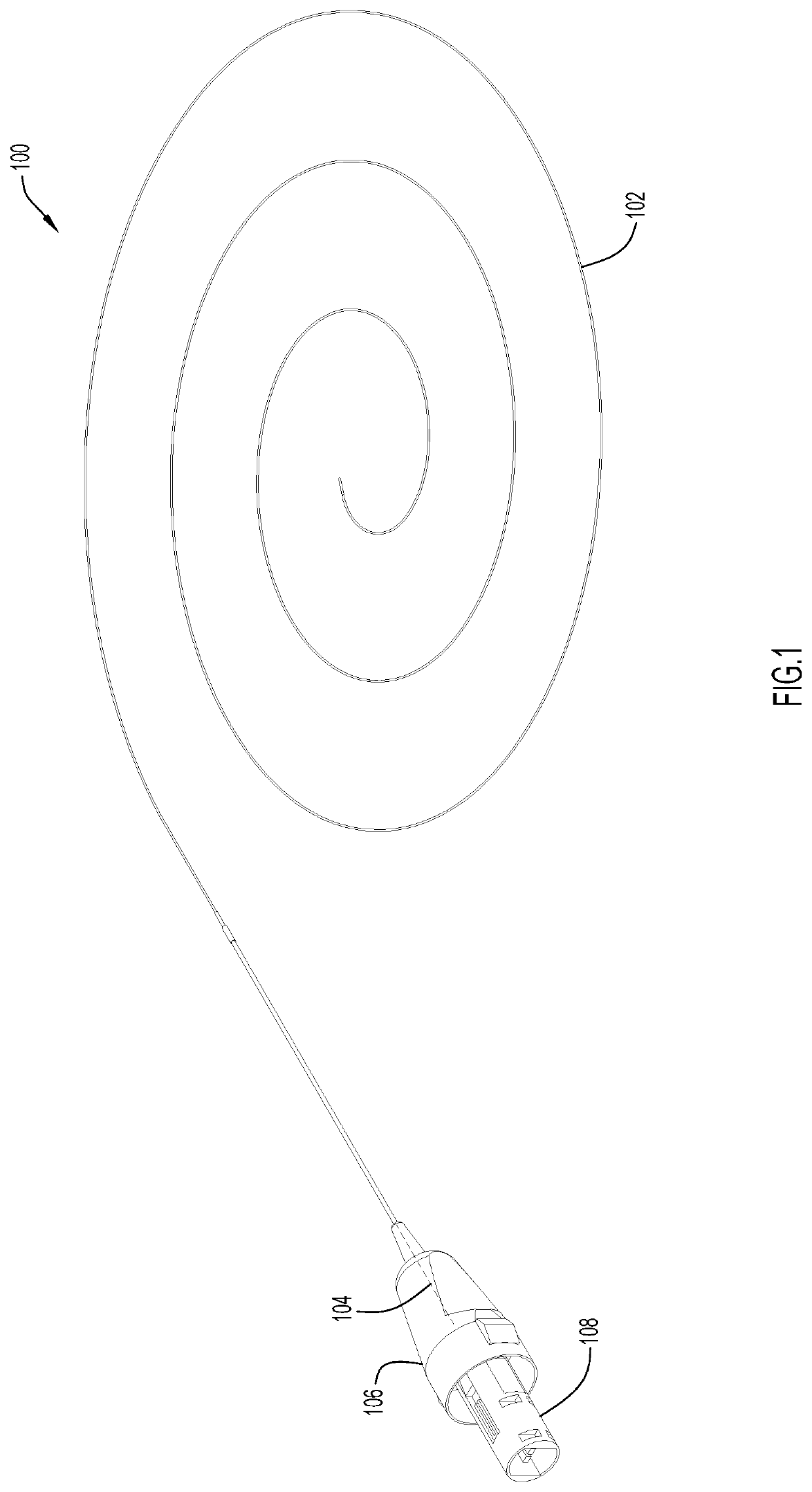
[0032]FIG. 1 is a perspective view of an imaging catheter 100 for an imaging catheter system with force error detection and remediation according to an example embodiment. Imaging catheter 100 includes an elongate tubular outer member or sheath 102 configured for insertion into the lumen of a vessel (e.g., using a guidewire), an elongate inner core in the form of a torque cable 104 configured to extend longitudinally within the outer sheath, and outer and inner hubs 106 and 108 at proximal ends of the outer sheath 102 and the torque cable 104, respectively. In the example shown in FIG. 1, the outer hub 106 is hollow, and the inner hub 108 is disposed at least partly within the outer hub and configured to be rotatable and linearly translatable relative to a longitudinal axis of the outer hub. The torque cable 104 extends distally from the inner hub 108 into the outer sheath 102.

[0033]In an example embodiment, the outer sheath 102 is composed of a flexible material that is efficiently...


PUM


Abstract

An intravascular imaging system includes a catheter with an elongate outer sheath and a torque cable axially translatable and rotatable in the elongate outer sheath, a pullback and rotation unit for axially translating and rotating the torque cable, a sensor configured to provide an output indicative of an axial force exerted by the torque cable on a rotor in the pullback and rotation unit, and a controller configured to cause the pullback and rotation unit to operate in a remedial mode if the output exceeds a predetermined threshold.

Description

FIELD OF THE INVENTION[0001]The present invention relates generally to catheters with movable cores and, more particularly, to systems and methods for detecting and remediating force error conditions in such catheters.BACKGROUND[0002]Catheters with imaging components are commonly used to inspect vessels in the body. Such catheters may include a hollow, tubular sheath made of a flexible material. The sheath may be placed in a vessel using a guidewire and used as a conduit for positioning imaging components in the vessel. For example, imaging components may be mounted at the distal end of a torque cable and advanced into the vessel via the sheath. Depending on the type of information desired, the imaging components may include optical elements such as mirrors or lenses for transmitting and receiving light energy (e.g., near infrared light) and / or transducers for transmitting and receiving sound energy (e.g., ultrasonic pulses). Imaging components may be mounted on an imaging tip at th...

Claims


Application Information

Patent Timeline
IPC IPC(8): A61M25/01A61M25/06A61B8/12A61B8/00A61B5/00
CPCA61M25/0662A61B8/445A61B5/0075A61B8/12A61B5/0084A61M25/0113A61M2205/332A61B5/02007A61B5/6852A61B5/0086A61B2562/0247
Inventor BARONE, DAVIDBITNER, TODDBECK, JOHN N.
Owner INFRAREDX INC
Why Eureka
Try Eureka