Laser machining system and method for controlling laser machining system

Inactive Publication Date: 2020-03-19
PANASONIC INTELLECTUAL PROPERTY MANAGEMENT CO LTD
View PDF0 Cites 1 Cited by
  • Summary
  • Abstract
  • Description
  • Claims
  • Application Information

AI Technical Summary

Benefits of technology

The present disclosure is about a laser machining system and a method for controlling it that can be used for both piercing processing and cutting-out processing. It also aims to improve accuracy by reducing speed variations at the connection points between a starting point and a desired cutting path.

Problems solved by technology

Thus, the method is useful for piercing of a specific shape, but is not applicable to cases where a specific shape is desired to be cut out.
Depending on mechanisms or principles of operation of laser cutting heads, simple operation of acceleration or deceleration may cause discontinuities of speed at a shifting point from an acceleration section to a cutting path section and / or a shifting point from the cutting path section to a deceleration section.
The laser cutting head may vibrate at these points exhibiting discontinuities of speed and may affect a cutting path.

Method used


Image

  • Laser machining system and method for controlling laser machining system
  • Laser machining system and method for controlling laser machining system
  • Laser machining system and method for controlling laser machining system

Examples


Embodiment Construction

[0040]An exemplary embodiment of a laser machining system and a method for controlling the laser machining system according to the present disclosure is described below with reference to the drawings.

[Configuration of Laser Machining System]

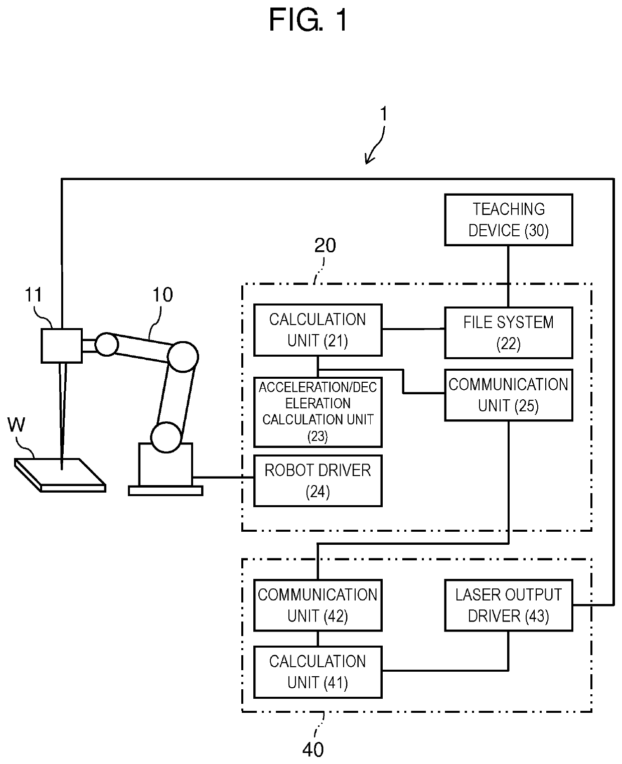
[0041]As shown in FIG. 1, a laser cutting system, which is an example of a laser machining system, includes one robot system 1 equipped with laser cutting head 11, and one laser oscillation device 40.

[0042]Robot system 1 includes manipulator 10, robot control device 20, and teaching device 30. Manipulator 10 is equipped with laser cutting head 11. Robot control device 20 is configured to control operation of manipulator 10 and laser cutting head 11, and causes laser cutting head 11 to emit laser light. This enables desired machining on a target object, i.e., workpiece W.

[0043]Robot control device 20 includes calculation unit 21, file system 22, acceleration / deceleration calculation unit 23, robot driver 24, and communication unit 25. Robot contro...


PUM

PropertyMeasurementUnit
Distanceaaaaaaaaaa

Abstract

A laser machining system includes: a robot with a laser cutting head having a plurality of degrees of freedom of motion at least in a two-dimensional plane; and a laser oscillation device configured to transmit laser light to the laser cutting head, the laser machining system being configured to cut a target object into a desired cutting shape by moving the laser cutting head, and further includes a controller configured to perform: a step of moving the laser cutting head along an arc-shaped path to cause laser light irradiation to move from an operation start point to a target-path-cutting start point, the operation start point being determined on a coordinate plane that defines the cutting shape, the target-path-cutting start point being located along the cutting shape (S7); a step of moving the laser cutting head to cause laser light irradiation to move from the target-path-cutting start point to a target-path-cutting end point located along the cutting shape (S8); and a step of moving the laser cutting head along an arc-shaped path to cause laser light irradiation to move from the target-path operation end point to an operation end point (S9).

Description

TECHNICAL FIELD[0001]The present disclosure relates to a laser machining system including: a robot with a laser cutting head having a plurality of degrees of freedom of motion at least in a two-dimensional plane; and a laser oscillation device configured to transmit laser light to the laser cutting head, the laser machining system being configured to cut a target object into a desired cutting shape by moving the laser cutting head, and relates to a method for controlling the laser machining system.BACKGROUND ART[0002]In recent years, laser machining techniques have been widely used in which energy of laser light is utilized for processing, such as cutting, on various kinds of target objects. This is because laser light has less thermal influence and scarcely causes deformation on target objects, and enables high-speed cutting of target objects.[0003]In addition, laser machining apparatuses capable of three-dimensional machining have been achieved by mounting a laser cutting head on ...

Claims


Application Information

Patent Timeline
IPC IPC(8): B23K26/38B23K26/08B25J9/16
CPCB23K26/38B23K26/0876B25J9/1651B23K26/0884B23K26/388
Inventor KOMATSU, TAKAMICHI
Owner PANASONIC INTELLECTUAL PROPERTY MANAGEMENT CO LTD
Why Eureka
Try Eureka