Methods of capping metallic bottles

a technology of metallic bottles and capping, which is applied in the field of manufacture and sealing of containers, can solve the problems of affecting the effectiveness of ingredients, the flavor, appearance or color of products, and the high speed of metallic container production lines, and achieves the effect of reducing top load and side load and less simultaneous for

Active Publication Date: 2020-03-19
BALL CORP
View PDF0 Cites 0 Cited by
  • Summary
  • Abstract
  • Description
  • Claims
  • Application Information

AI Technical Summary

Benefits of technology

[0020]The present invention provides novel apparatus and methods that apply less simultaneous force to metallic bottles during the sealing of the metallic bottles than prior art sealing apparatus and methods. It is one aspect of the present invention to provide a novel method and apparatus that applies a reduced top load and side load during the sealing of a metallic bottle with a ROPP closure.
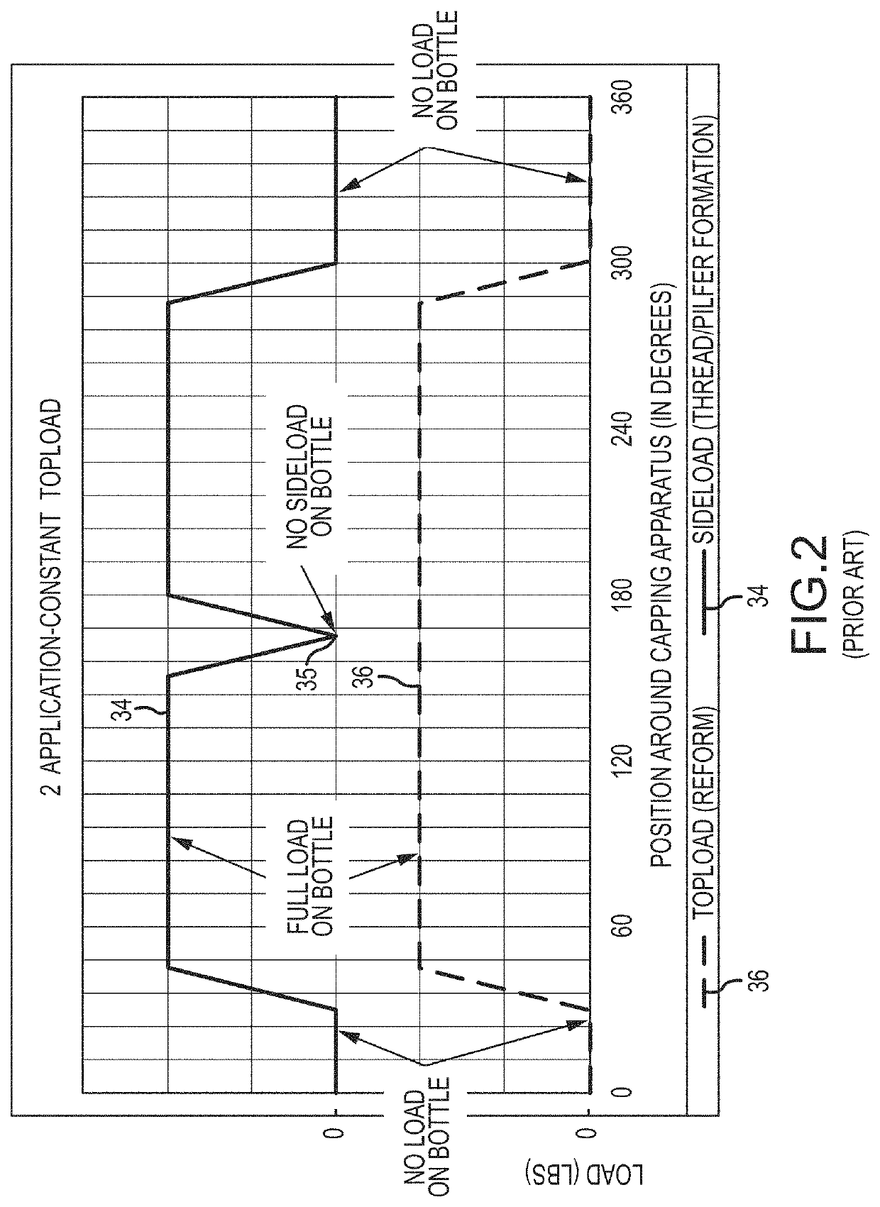
[0022]Still another aspect is to provide a method and apparatus in which the topload is reduced after a pressure block of a capping apparatus of the present invention forms a channel in a ROPP closure positioned on a metallic bottle. In one embodiment, after an initial maximum topload force is applied by the capping apparatus, the topload force is decreased to a minimum amount sufficient to maintain a seal between the metallic bottle and the ROPP closure while operations generating sideload forces are performed.
[0024]Another aspect of the present invention is a method and a capping apparatus that increases the number of forming passes performed by thread rollers to form closure threads on a ROPP closure. In one embodiment, the capping apparatus includes more thread rollers than prior art capping apparatus. In another embodiment, the capping apparatus includes two thread rollers that each perform three or more passes to form the closure threads. Each thread roller of the capping apparatus of the present invention applies less sideload force to the ROPP closure and metallic bottle than prior art thread rollers.
[0035]Yet another aspect of the present invention is a metallic bottle sealed by a ROPP closure with a capping apparatus of an embodiment of the present invention that applies less cumulative force to the metallic bottle than prior art capping apparatus. The metallic bottle includes, but is not limited to: (1) a bottom portion that is closed; (2) a body portion extending upwardly from the bottom portion; (3) a neck portion with a reduced diameter extending upwardly from the body portion; (4) bottle threads formed on a portion of the neck portion; (5) an opening positioned on an uppermost portion of the neck portion; and (6) a ROPP closure that seals the opening, the ROPP closure including a channel and closure threads formed by a capping apparatus. Optionally, in one embodiment of the present invention, at least one of the ROPP closure and the metallic bottle are rotated in a closing direction after the closure threads are at least partially formed such that a distance from the bottom portion of the metallic bottle to an exterior surface portion of the ROPP closure is decreased.
[0040]In one embodiment, the metallic bottle is configured to store a pressurized beverage with a maximum internal pressure of up to about 100 pounds per square inch without unintended venting of product from the metallic bottle. In another embodiment, the maximum internal pressure is up to about 135 pounds per square inch without failure or blow-off of the ROPP closure.
[0061]As used herein, the phrase “light-weight metallic bottle” refers to a metallic bottle formed of a reduced amount of metal material than prior art metallic bottles. Accordingly, light-weight metallic bottles have a reduced material thickness in one or more predetermined portions of the metallic bottle compared to prior art metallic bottles. In some embodiments, the light-weight metallic bottle is both thinner (i.e., less gage) and has less mass than prior art metallic bottles. In one embodiment, at least a portion of the metallic bottle has a thickness that is approximately 95% of the thickness of a corresponding portion of a prior art metallic bottle formed of the same material. In another embodiment, the light weight metallic bottle has a column strength that is about 91% of the column strength of a prior art metallic bottle form of the same material. In embodiments, the metal material comprises aluminum. In one embodiment, a light-weight metallic bottle is comprised of a different aluminum alloy than prior art metallic bottles comprised of aluminum alloys. For example, in one embodiment the light-weight metallic bottle is comprised of an alloy that has a column strength that is about 85% of the column strength of prior art alloys used to form metallic bottles. It will be appreciated by one of skill in the art that a light-weight metallic bottle formed of even slightly less material compared to a prior art metallic bottle will save manufacturers, bottlers, and shippers millions of dollars annually based on the billions of metallic bottles currently produced annually. Similarly, forming metallic bottles of even a marginally less expensive alloy will result in a significant annual cost reduction for manufacturers and bottlers.

Problems solved by technology

For example, the metallic body prevents CO2 migration and transmission of UV radiation which may damage the contents of the metallic container and negatively influence the effectiveness of ingredients, as well as the flavor, appearance, or color of the product.
Further, some consumers avoid plastic containers due to concerns that the plastic may leach chemicals into consumable products.
Because of the high speeds of the production lines, techniques or processes that may work in other industries or with containers formed of other materials do not necessarily work at the high speeds required for metallic container production lines.
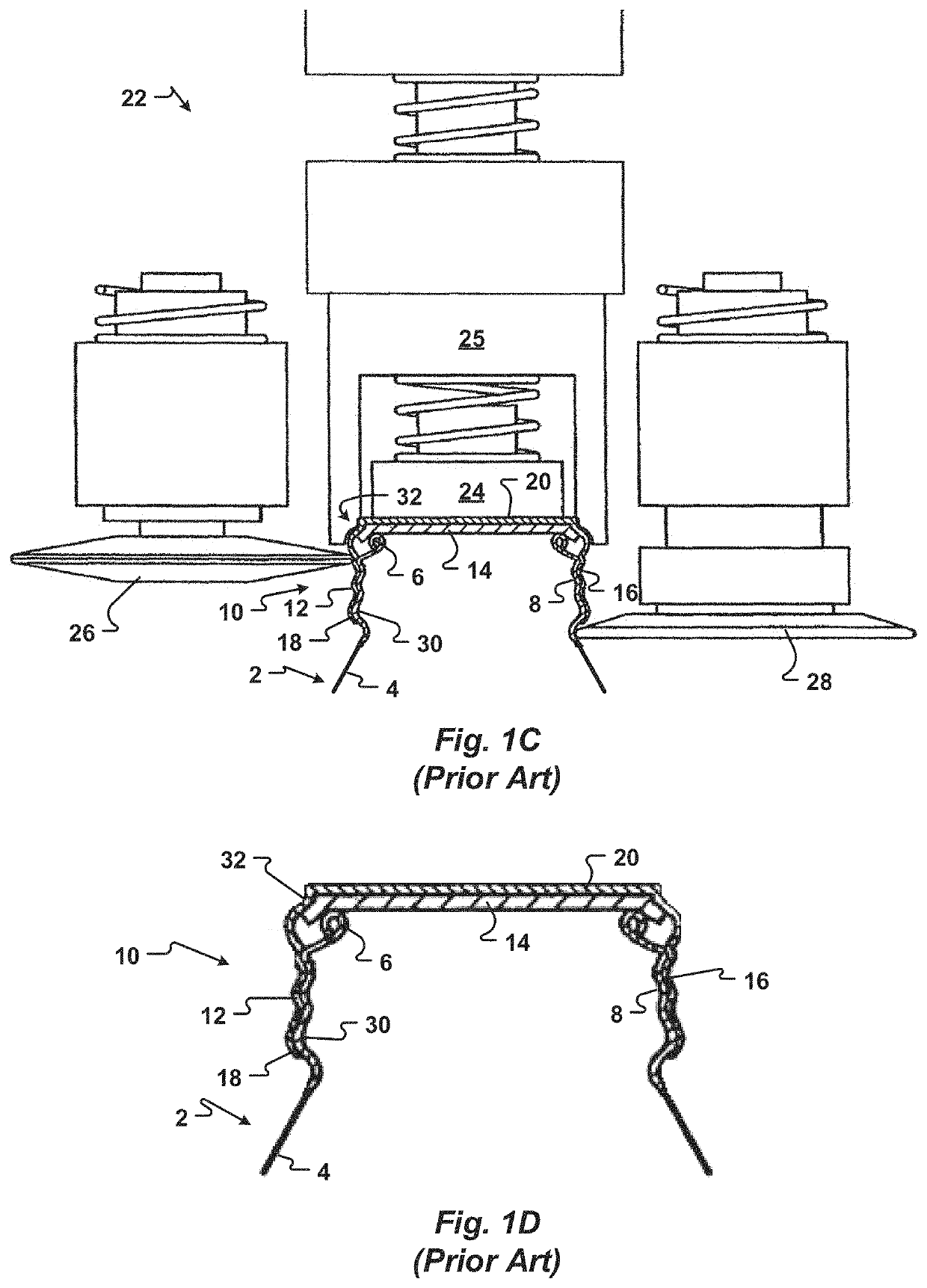
Failures are possible when a greater than the nominal topload is used with a nominal sideload.
Another failure observed when too much topload is used is deformation of the metallic bottle 2.
Still another failure associated with the use of too much topload is ROPP closures 10 that are undesirably difficult to remove from metallic bottles 2.
A less than nominal topload may result in a failure due to substandard sealing of the metallic bottle 2.
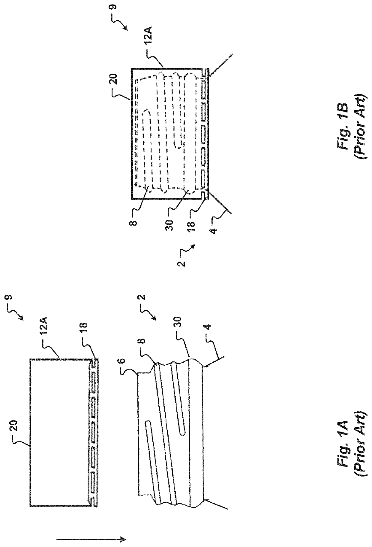
This can result in insufficient contact of the ROPP liner 14 with the bottle curl 6 and a failure to seal the metallic bottle 2.
Another failure caused by the use of too little topload is loss of seal of the metallic bottle 2 by movement of the ROPP closure 10.
This can result in venting of the content of the metallic bottle 2.
Although less than the cumulative load applied to glass bottles sealed with ROPP closures, these loads are almost excessive for current metallic bottles 2.
The small production window results in overstress and failures of the metallic bottle 2 or the ROPP closure 10 when the capping apparatus 22 is out of calibration or for marginal metallic bottles 2.
Due to the limitations associated with known methods and prior art apparatus used to seal metallic bottles, there is an unmet need for methods and apparatus of sealing metallic bottles that apply less force to the metallic bottle to achieve a seal.

Method used


Image

  • Methods of capping metallic bottles
  • Methods of capping metallic bottles
  • Methods of capping metallic bottles

Examples


Embodiment Construction

[0081]The present invention has significant benefits across a broad spectrum of endeavors. It is the Applicant's intent that this specification and the claims appended hereto be accorded a breadth in keeping with the scope and spirit of the invention being disclosed despite what might appear to be limiting language imposed by the requirements of referring to the specific examples disclosed. To acquaint persons skilled in the pertinent arts most closely related to the present invention, a preferred embodiment that illustrates the best mode now contemplated for putting the invention into practice is described herein by, and with reference to, the annexed drawings that form a part of the specification. The exemplary embodiment is described in detail without attempting to describe all of the various forms and modifications in which the invention might be embodied. As such, the embodiments described herein are illustrative, and as will become apparent to those skilled in the arts, may be...


PUM

PropertyMeasurementUnit
depthaaaaaaaaaa
depthaaaaaaaaaa
weightaaaaaaaaaa

Abstract

Methods of sealing a metallic container are provided. More specifically, the present invention relates to methods that reduce the amount of force applied to a metallic bottle to seal the metallic bottle with a ROPP closure. The methods include use of a capping apparatus that may include more thread rollers than known capping apparatus. Optionally, the thread rollers may use more forming passes to form threads on the ROPP closure. The capping apparatus may also rotate one or more of the ROPP closure and the metallic container in a closing direction before the metallic container is discharged. In one embodiment, the thread rollers form the closure threads before or after a pilfer roller applies a sideload to the ROPP closure.

Description

CROSS-REFERENCE TO RELATED APPLICATIONS[0001]This application is a divisional application and claims the benefit and priority of U.S. patent application Ser. No. 15 / 236,174 filed Aug. 12, 2016, and entitled “Apparatus and Methods of Capping Metallic Bottles,” which is incorporated herein in its entirety by reference.FIELD OF THE INVENTION[0002]The present invention relates generally to the manufacture and sealing of containers. More specifically, this invention provides an apparatus and methods used to seal metallic containers with Roll-on Pilfer Proof (ROPP) closures.BACKGROUND[0003]Metallic containers offer distributors and consumers many benefits. The metallic body of a metallic container provides optimal protection properties for products. For example, the metallic body prevents CO2 migration and transmission of UV radiation which may damage the contents of the metallic container and negatively influence the effectiveness of ingredients, as well as the flavor, appearance, or col...

Claims


Application Information

Patent Timeline
Patent Type & Authority Applications(United States)
IPC IPC(8): B67B3/20B65D1/02B67B3/18
CPCB65D1/0246B67B3/2066B67B3/18
Inventor ROSS, JOHN R.BONFOEY, DAVID J.
Owner BALL CORP
Why Eureka
Try Eureka