
Wind Farm Topology and Method of Operating the Same

a topology and wind farm technology, applied in the field of wind farm, can solve the problems of large foot print, large wind farm configuration, and large loss in annual energy production of wind farm,

Active Publication Date: 2020-03-19
GENERAL ELECTRIC CO
View PDF0 Cites 0 Cited by
  • Summary
  • Abstract
  • Description
  • Claims
  • Application Information

AI Technical Summary

Benefits of technology

The patent describes a wind farm with multiple wind turbine stations and a control system. The control system includes a control system that determines the wind speed and estimates the frequency of the wind turbine stations' generators. It then calculates the desired frequency and sends control signals to a power converter to update the line frequency of the power bus. This ensures that the desired frequency is within the frequency compensation ranges of the wind turbine station power converters, leading to more efficient power generation. The technical effect of the patent is improved performance and efficiency of wind farms through optimized power generation.

Problems solved by technology

Typically, such wind farms suffer from losses in an annual energy production (AEP) due to variations in wind speed in the wind farm.
In certain situations, the full power conversion based wind farms are also prone to losses in the AEP due to variations in the wind speed in the wind farms.
Such a configuration of the partial power converter tends to be bulky and requires a large foot print.
Additionally, in many wind turbine stations, the DFIG is coupled to the grid via an expensive three-winding step-up transformer.

Method used


Image

  • Wind Farm Topology and Method of Operating the Same
  • Wind Farm Topology and Method of Operating the Same
  • Wind Farm Topology and Method of Operating the Same

Examples


Embodiment Construction

[0012]In the following specification and the claims, the singular forms “a”, “an” and “the” include plural referents unless the context clearly dictates otherwise. As used herein, the term “or” is not meant to be exclusive and refers to at least one of the referenced components being present and includes instances in which a combination of the referenced components may be present, unless the context clearly dictates otherwise.

[0013]As used herein, the terms “may” and “may be” indicate a possibility of an occurrence within a set of circumstances; a possession of a specified property, characteristic or function; and / or qualify another verb by expressing one or more of an ability, capability, or possibility associated with the qualified verb. Accordingly, usage of “may” and “may be” indicates that a modified term is apparently appropriate, capable, or suitable for an indicated capacity, function, or usage, while taking into account that in some circumstances, the modified term may some...


PUM


Abstract

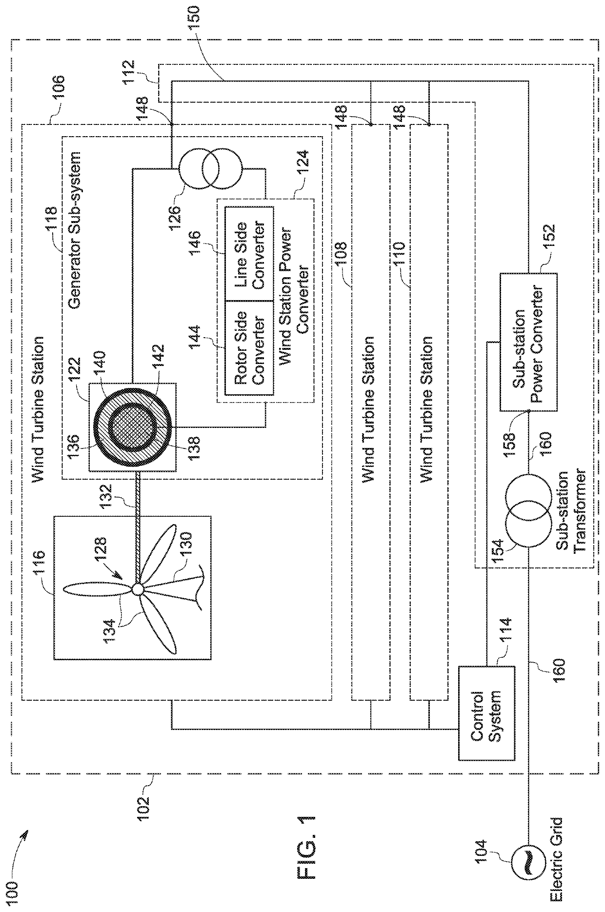
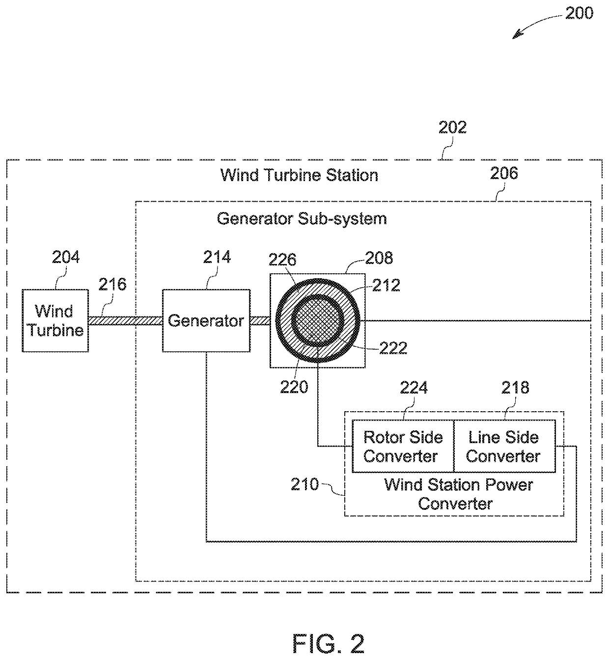
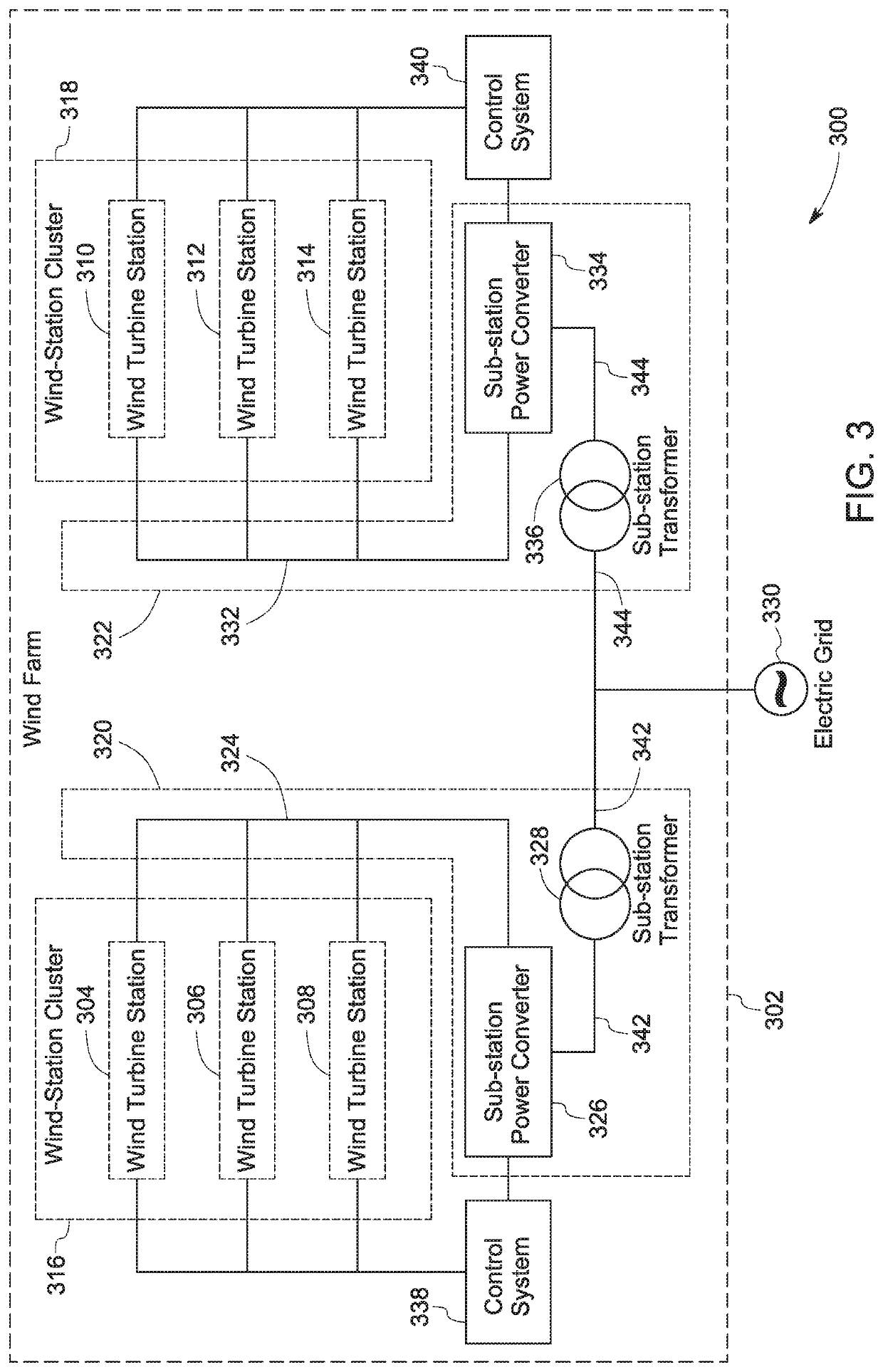
A wind farm is presented. The wind farm includes a plurality of wind turbine stations, where each wind turbine station includes a wind turbine and a generator sub-system. The generator sub-system includes a doubly-fed induction generator configured to generate an alternating current voltage and a wind turbine station power converter. The wind farm further includes a power collection sub-system that includes a power bus and a sub-station power converter. The wind farm also includes a control system configured to determine a wind speed metric, estimate a corresponding frequency metric, calculate a desirable frequency based on the wind speed metric and frequency compensation ranges of the wind turbine station power converters, and generate and communicate control commands to the sub-station power converter based on the desirable frequency to allow the sub-station power converter to update a line frequency of a power bus voltage based on the desirable frequency.

Description

BACKGROUND[0001]Embodiments of the present specification generally relate to a wind farm and in particular, to a wind farm topology and method of operating the wind farm.[0002]A wind farm typically includes a plurality of wind turbine stations, such as wind turbine towers, capable of converting a kinetic energy of wind into electrical power. Currently, wind farms having different configurations are used to generate the electrical power. In general, these wind farms include one or more of wind turbine stations operable at a fixed speed, wind turbine stations performing full power conversion, and wind turbine stations performing partial power conversion.[0003]The wind farms having wind turbine stations operable at the fixed speed generally include an asynchronous generator and a wind turbine level step-up transformer. Typically, such wind farms suffer from losses in an annual energy production (AEP) due to variations in wind speed in the wind farm. Moreover, the wind farms having the ...

Claims


Application Information

Patent Timeline
Patent Type & Authority Applications(United States)
IPC IPC(8): F03D7/04F03D7/02H02J3/38
CPCF03D7/0272F03D7/048F03D7/0284F05B2270/337H02J3/386H02J2300/28H02J3/381Y02E10/76Y02E10/72H02J3/40H02J3/38
Inventor GANIREDDY, GOVARDHANDATTA, RAJIB
Owner GENERAL ELECTRIC CO
Learn More