Reduction Gearbox Transmission Separation Mechanism

a transmission separation and gearbox technology, applied in the direction of wheelchair/patient conveyance, inter-engaging clutch, gearing, etc., can solve the problem of difficulty in pushing the electrically powered wheelchair

Active Publication Date: 2020-03-19
ZHEJIANG LINIX MOTOR
View PDF3 Cites 5 Cited by
  • Summary
  • Abstract
  • Description
  • Claims
  • Application Information

AI Technical Summary

Benefits of technology

[0016]The foregoing arrangement realizes the movement of the rotating protrusion only when the driving rotating block rotates clockwise, and makes the driving rotating block revolved on the driven rotating block when the driving rotating block rotates anticlockwise, thereby preventing the driven rotating block from exerting a force on the fixed block, so as to protect the structure stability of parts of the present invention.
[0017]Preferably, the rotating protrusion is cylindrical, and a cambered surface of the rotating protrusion is in contact with the axial surface of the first protrusion or the axial surface of the second protrusion. The foregoing arrangement reduces a contact area between the rotating protrusion and the fixed block, in order for the rotation of the rotating block.
[0018]Preferably, the limiting portion and the moving block are split, the limiting portion is annular, a clamping spring is fixed to an end, away from the linkage gear, of the moving block, and the limiting portion is limited between the clamping spring and the axial surface, away from the linkage gear, of the rotating block. The foregoing arrangement is convenient for limiting the rotating block between the limiting portion and a fixing portion, and convenient for assembling parts of the present invention.
[0019]The present invention has the advantage that a transmission failure of a reduction gearbox can be implemented in order to push an electrically powered wheelchair in the case of motor outage.

Problems solved by technology

When an electrically powered wheelchair is used, it is difficult to push the electrically powered wheelchair in the case of motor outage due to the self-locking force of the reduction gearbox.

Method used


Image

  • Reduction Gearbox Transmission Separation Mechanism
  • Reduction Gearbox Transmission Separation Mechanism
  • Reduction Gearbox Transmission Separation Mechanism

Examples


Embodiment Construction

[0027]The present invention is further described hereinafter according to the drawings and specific embodiments.

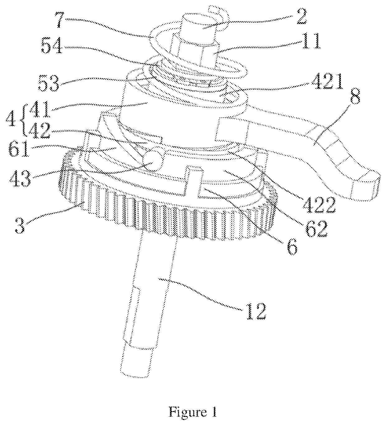
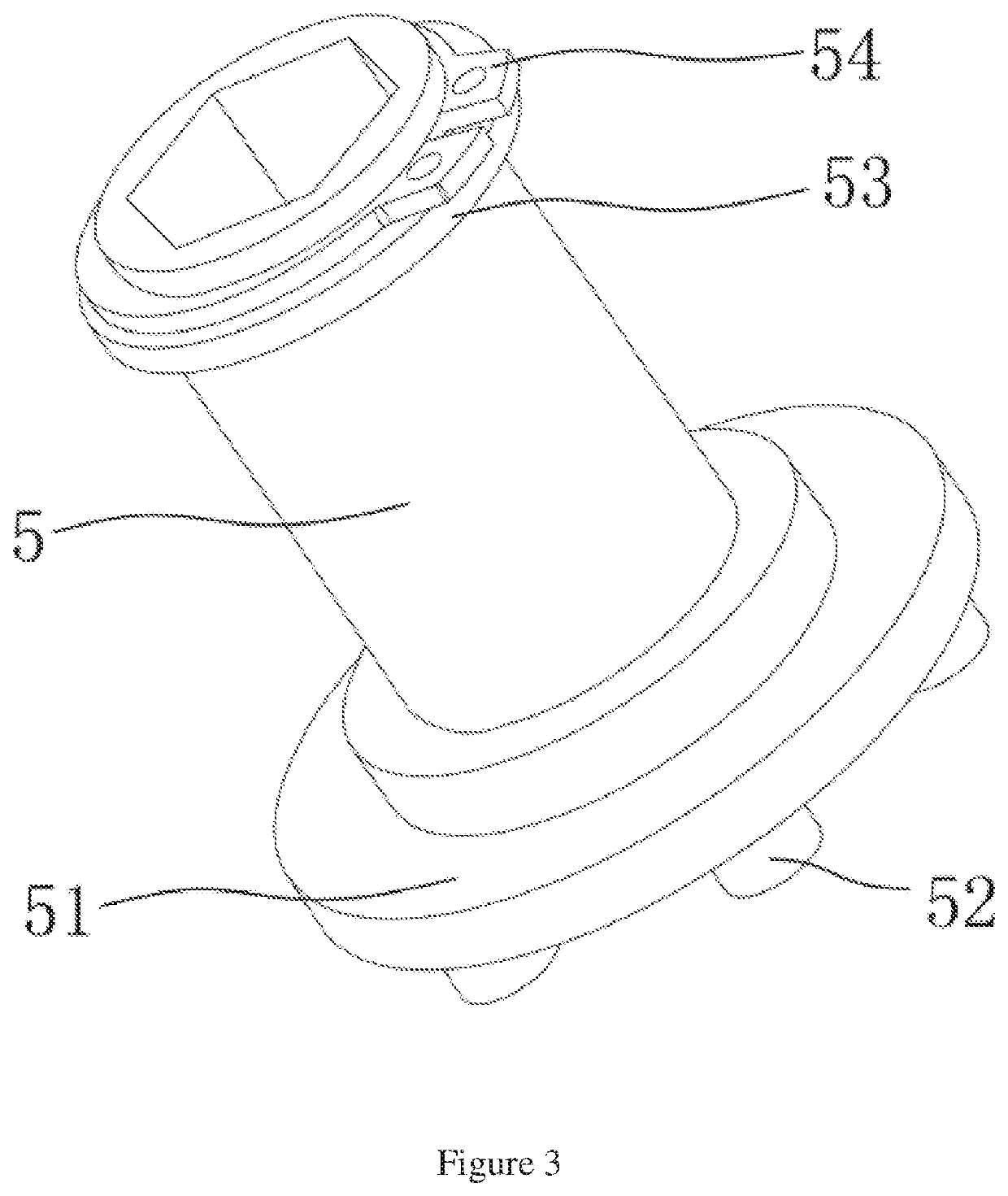
[0028]As shown in FIG. 1 to FIG. 7, a reduction gearbox transmission separation mechanism of the present invention includes a box 1, A first shaft 2 and a second shaft are disposed in the box 1. The first shaft 1 is sleeved with a linkage gear 3, a rotating block 4, a moving block 5, and a fixed block 6. The linkage gear 3 is used for linking the first shaft 2 and the second shaft. The linkage gear 3 is a transmission part in a gear transmission assembly or a worm wheel and worm transmission assembly or a gear worm transmission assembly.

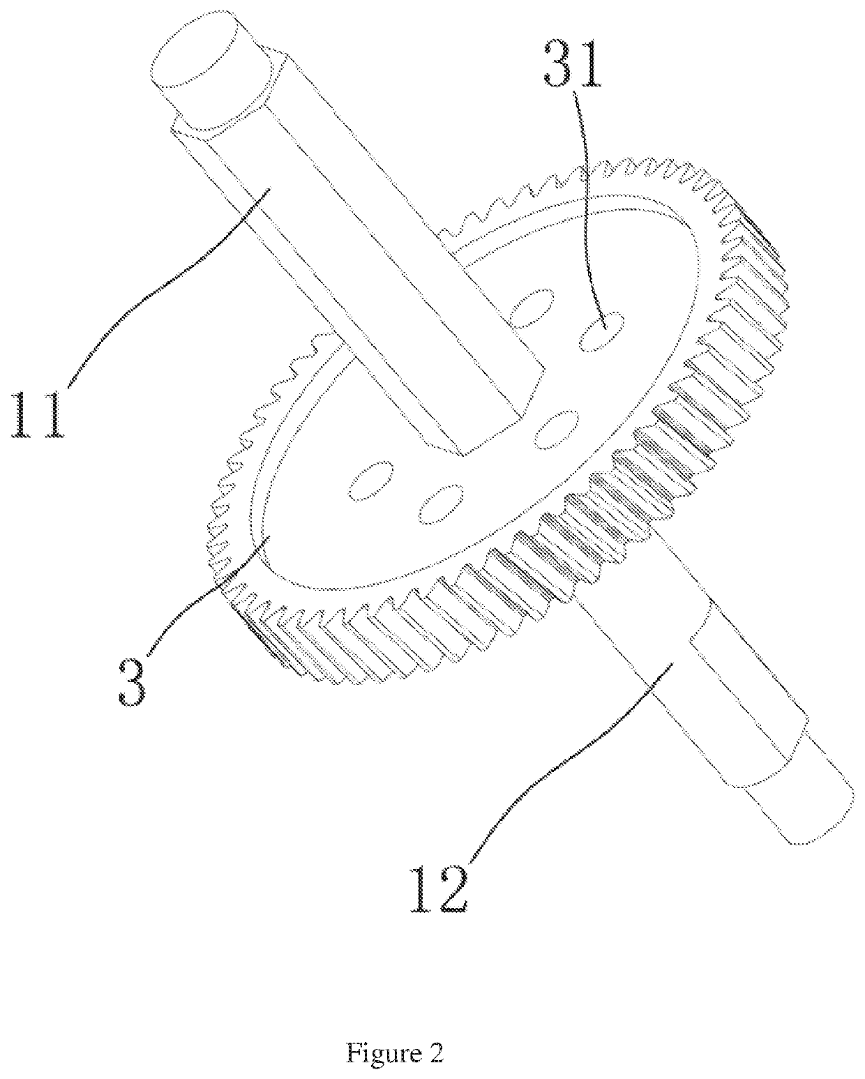
[0029]As shown in FIG. 1 to FIG. 4, the first shaft 1 includes a linkage segment 11 and a fitting segment 12. The linkage gear 3 is rotatably sleeved on the fitting segment 12. An inner edge of an inner hole of the linkage gear 3 and an outer edge of the fitting segment 12 of the first shaft are both circular. The moving block 4 is disposed...


PUM


Abstract

A reduction gearbox transmission separation mechanism includes a box. A first shaft and a second shaft are disposed in the box. The first shaft is sleeved with a linkage gear, a rotating block, a moving block, and a fixed block. The linkage gear is used for linking the first shaft and the second shaft. The linkage gear is a transmission part in a gear transmission assembly or a worm wheel and worm transmission assembly or a gear worm transmission assembly. The first shaft includes a linkage segment and a fitting segment. The linkage gear is rotatably sleeved on the fitting segment. The moving block is disposed on the linkage segment, and the moving block is axially movable along the linkage segment.

Description

CROSS REFERENCE TO RELATED APPLICATIONS[0001]The present application claims the benefit of Chinese Patent Application No. 201811096675.5 filed on Sep. 19, 2018, the contents of which are incorporated herein by reference in its entirety.TECHNICAL FIELD[0002]The present invention relates to a reduction gearbox, and more particularly relates to a reduction gearbox transmission separation mechanism.BACKGROUND ART[0003]An existing reduction gearbox includes an input shaft and an output shaft. The input shaft is linked with the output shaft through a transmission assembly. The transmission assembly is a gear transmission assembly or a worm wheel and worm transmission assembly or a gear worm transmission assembly, which has a certain self-locking force. When an electrically powered wheelchair is used, it is difficult to push the electrically powered wheelchair in the case of motor outage due to the self-locking force of the reduction gearbox.SUMMARY OF THE INVENTION[0004]An object of the p...

Claims


Application Information

Patent Timeline
Patent Type & Authority Applications(United States)
IPC IPC(8): F16D11/14F16D23/12
CPCF16D23/12F16H1/16F16D11/14A61G5/04F16D2023/123F16D11/00F16D2011/004
Inventor WANG, FENG
Owner ZHEJIANG LINIX MOTOR
Why Eureka
Try Eureka