Lidar system

Pending Publication Date: 2020-03-19
ELECTRONICS & TELECOMM RES INST
View PDF5 Cites 2 Cited by
  • Summary
  • Abstract
  • Description
  • Claims
  • Application Information

AI Technical Summary

Benefits of technology

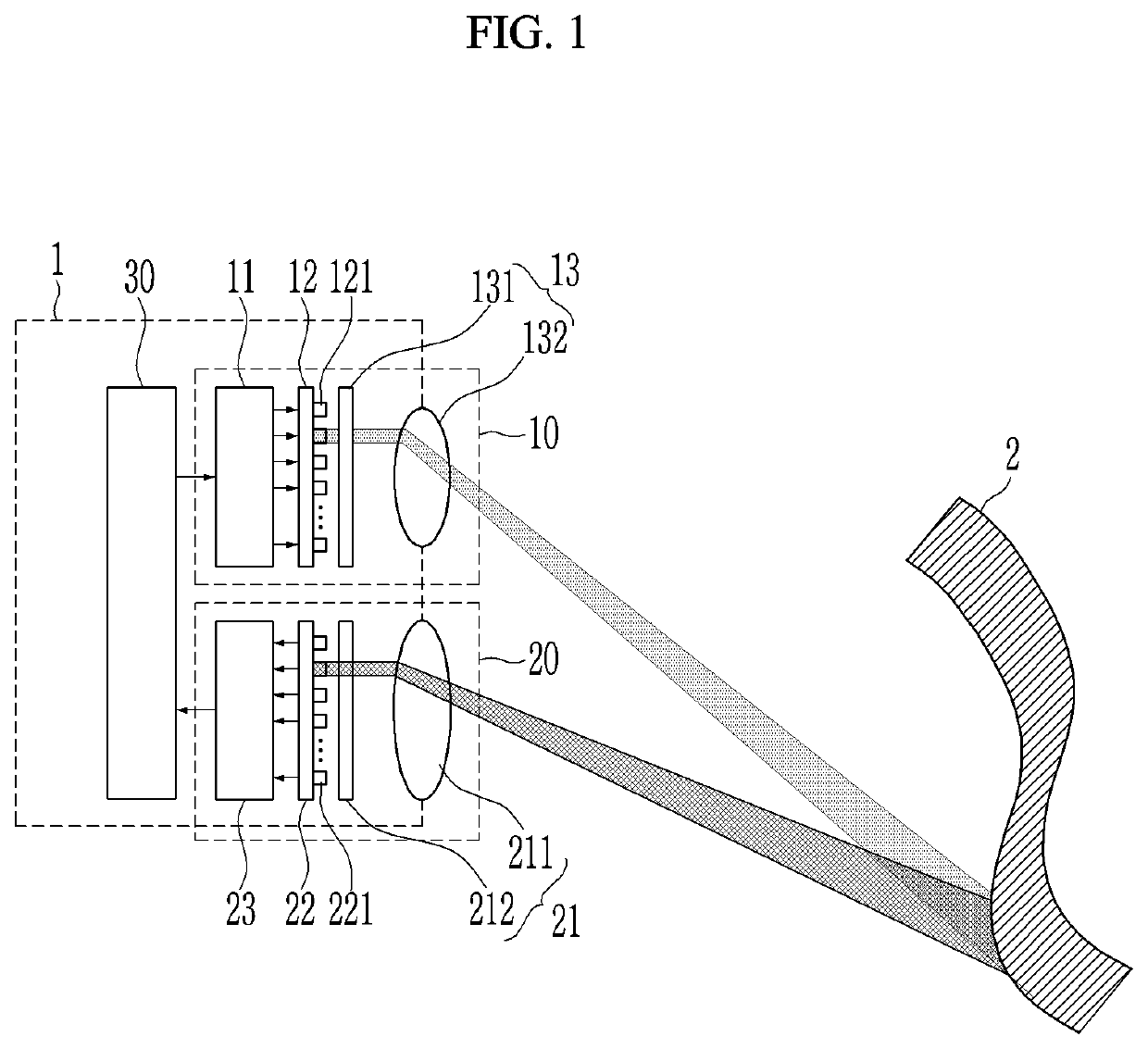
The present invention provides a LIDAR system that has advantages of receiving and reflecting light without needing to move the components mechanically. Additionally, the system operates efficiently by adjusting the timing of the light receiver based on the position of the transmission beam.

Problems solved by technology

The LIDAR of the rotary type was promoted to the fastest commercialization due to its simple structure, but it takes up a considerable volume by the motion of the motor itself, and it has a limitation in overcoming various problems resulting from the rotation itself, such that it is hard to make the durability superior.
In addition, even when a 3D image having an angle of about 120 degrees rather than 360 degrees is to be obtained at the installation point, there is a problem in the structure itself that the 360-degree rotation cannot be eliminated due to the characteristics of the rotation.
As a result, the LIDAR of the rotary type is not advantageous in terms of durability, miniaturization, and diversity of receiving structures.
However, the method of spreading light drastically reduces the amount of reflected light per unit area of the reflection point, and consequently the reflected light acts as a factor to make the amount of received light very small.
When using a high power light source, the durability of the entire sensor becomes poor during the transmission and reception of a high power laser, and high power lasers have a limited pulse repetition frequency (PRF).
This limitation of the PRF has a disadvantage in that it does not provide a 3D image of a high rate frame.
Since it is necessary to store the detection information of individual pulses in a small area, it is difficult to make a pixel having excellent characteristics, and thus there is a problem in that receiving large power laser light is required and eventually a higher laser power is required.
The rotary type and the array type have been used for a long time, but they are not suitable for trends such as the recent trend of miniaturization, durability improvement, and low cost of the LIDAR.
However, this approach causes three major problems.
Firstly, the method of changing the medium is controlled by temperature, and there is a problem that it is not easy to keep the control constant and stable.
Since the change of the external temperature affects the operation, it is difficult to control the correction of the operation.
Secondly, although light of different phases can be collected and propagated in one direction, harmonics are inevitably generated and there is a problem in that there is a side beam in which light (laser) is output in directions other than the main direction.
In the active method of receiving light (laser) after transmitting the light (laser), at least the relative output of the side beam should be greatly reduced depending on the distance, which is also not easy.
For example, in order to simultaneously perform 1 m detection and 100 m detection, the size of the side beam should be controlled to at least 40 dB or less, which is difficult to control.
Therefore, most OPA-type LIDAR has a problem in that it is difficult to increase the maximum detection distance.
Third, since it is difficult to increase the size of the output light (laser) due to the reasons described above, there is a problem in that the sensitivity of the reception light detector must be increased very much in order to increase the detection distance.
The problem with this method is that it is sensitive to changes in illuminance such as sunlight, and also relies on expensive optical filters to overcome such problems.

Method used


Image

  • Lidar system
  • Lidar system
  • Lidar system

Examples


Embodiment Construction

[0039]In the following detailed description, only certain exemplary embodiments of the present invention have been shown and described, simply by way of illustration. As those skilled in the art would realize, the described embodiments may be modified in various different ways, all without departing from the spirit or scope of the present invention. Accordingly, the drawings and description are to be regarded as illustrative in nature and not restrictive. Like reference numerals designate like elements throughout the specification.

[0040]Throughout the specification, in addition, unless explicitly described to the contrary, the word “comprise” and variations such as “comprises” or “comprising” will be understood to imply the inclusion of stated elements but not the exclusion of any other elements.

[0041]The expressions described in the singular may be interpreted as singular or plural unless an explicit expression such as “one”, “single”, and the like is used.

[0042]In addition, terms ...


PUM


Abstract

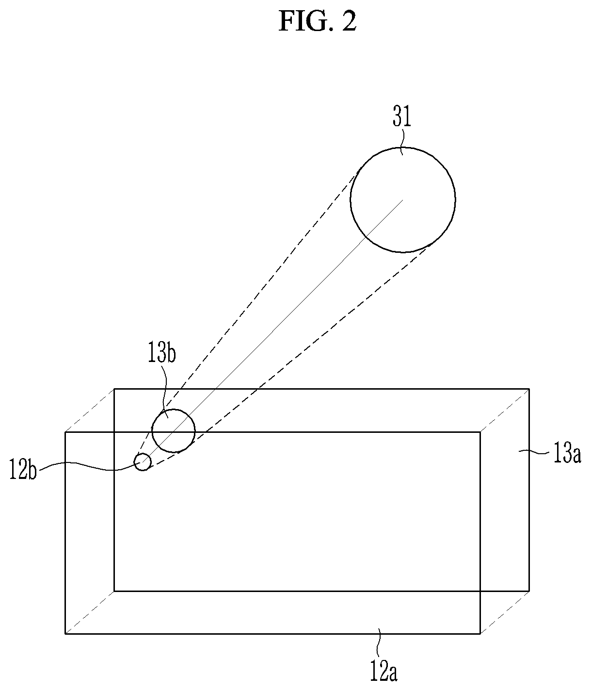
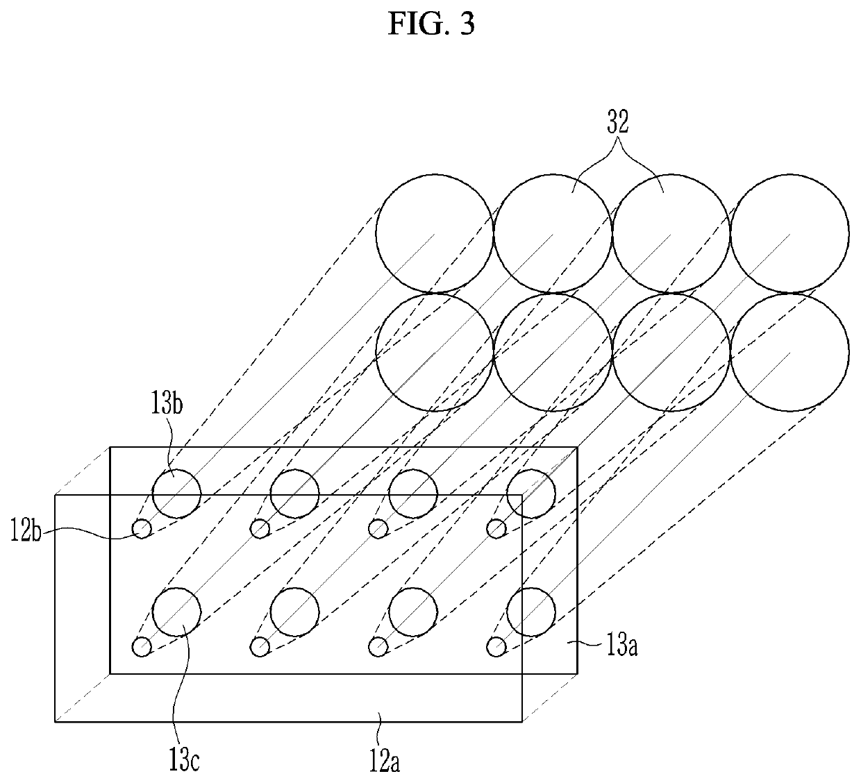
A LIDAR system is provided. The LIDAR system includes: a light transmitting unit configured to drive a plurality of light emitting elements by light emitting units to irradiate light to different positions of a target object; and a light receiving unit configured to detect light that is reflected at different positions of the target object and then is incident to different light receiving positions through a plurality of light receiving regions.

Description

CROSS-REFERENCE TO RELATED APPLICATION[0001]This application claims priority to and the benefit of Korean Patent Application No. 10-2018-0112509 filed in the Korean Intellectual Property Office on Sep. 19, 2018, the entire contents of which are incorporated herein by reference.BACKGROUND OF THE INVENTION(a) Field of the Invention[0002]The present invention relates to a Laser Imaging, Detection, and Ranging (LIDAR) system.(b) Description of the Related Art[0003]LIDAR (also referred to as Light Detection And Ranging), which shoots light (laser), then analyzes the light reflected by a target in front thereof, and then provides accurate information about the target object, is the most efficient means of obtaining a three-dimensional image. When using light (laser), LIDAR is attracting the most attention as a three-dimensional image sensor using light (laser) because generating energy and concentrating and transmitting this energy is implemented in a much smaller size in compared to conv...

Claims


Application Information

Patent Timeline
IPC IPC(8): G01S7/481G01S17/89G01S7/486
CPCG01S17/89G01S7/4863G01S7/4817G01S7/4815G01S7/4814G01S7/4816G01S17/894G01S7/497
Inventor MHEEN, BONGKISEO, HONG-SEOKCHOI, GYU DONG
Owner ELECTRONICS & TELECOMM RES INST
Why Eureka
Try Eureka