Ink Jet Recording Apparatus

a recording apparatus and ink jet technology, applied in the direction of printing, other printing apparatus, etc., can solve the problems of deterioration of print quality, contamination of deflecting electrodes, and inability to clean ink adhering to the outside of the nozzle and the like, and achieve the effect of stable operation

Active Publication Date: 2020-04-02
HITACHI IND EQUIP SYST CO LTD
View PDF2 Cites 3 Cited by
  • Summary
  • Abstract
  • Description
  • Claims
  • Application Information

AI Technical Summary

Benefits of technology

[0007]An object of the invention is to provide an ink jet recording apparatus that can perform a stable operation for cleaning a print head regardless of the level of skill of a worker.
[0009]According to the invention, it is possible to provide an ink jet recording apparatus that can perform a stable operation for cleaning a print head regardless of the level of skill of a worker.

Problems solved by technology

However, the cleaning of ink adhering to the outside of the nozzle and the like is not considered.
For this reason, there is a concern that the deflecting electrodes may be contaminated.
Accordingly, there is a possibility that print quality may deteriorate in a case where the deflecting electrodes are left in this state.
However, since the suppression of the contamination is not perfect, some kind of cleaning is necessary.
However, this operation for cleaning a print head has a problem that working hours required for the operation for cleaning a print head or the degree of removal of ink dirt after the completion of the operation for cleaning a print head may vary according to the level of skill of a worker.

Method used


Image

  • Ink Jet Recording Apparatus
  • Ink Jet Recording Apparatus
  • Ink Jet Recording Apparatus

Examples


first embodiment

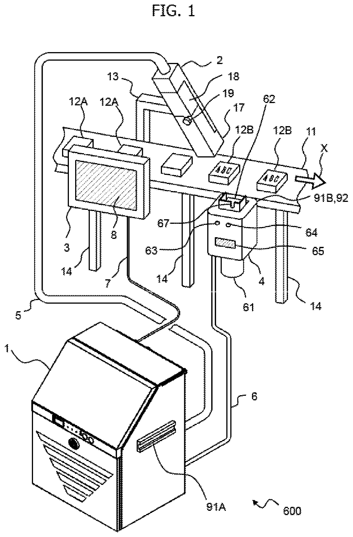
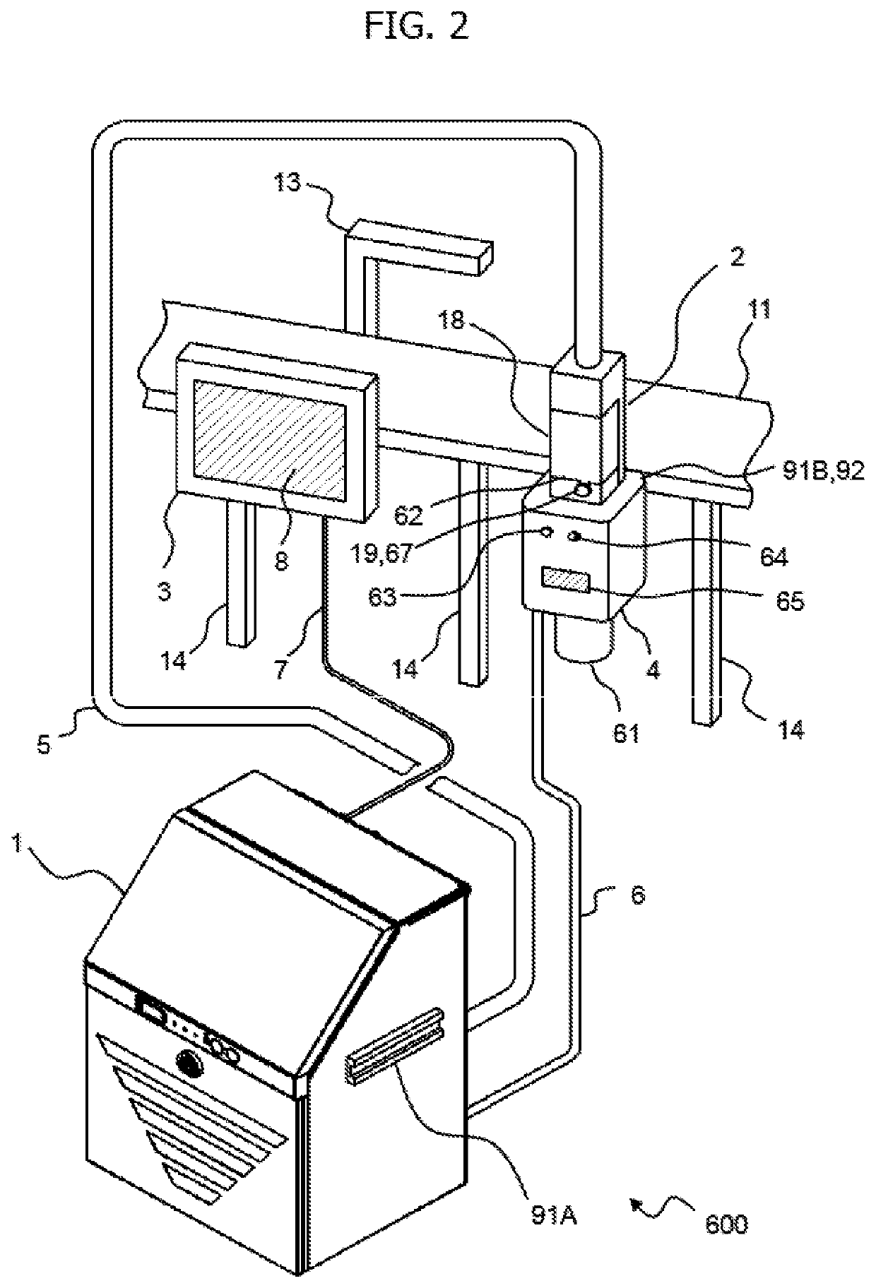
[0029]A state where an ink jet recording apparatus 600 according to this embodiment is used will be described with reference to FIGS. 1 and 2. FIG. 1 is a perspective view illustrating a state where the ink jet recording apparatus 600 according to this embodiment is used, and FIG. 2 is a perspective view illustrating a state where a print head 2 is mounted on a head cleaning unit 4 in the ink jet recording apparatus 600 according to this embodiment.

[0030]First, as illustrated in FIG. 1, the ink jet recording apparatus 600 includes an ink jet recording apparatus body 1, a print head 2 that is connected to the ink jet recording apparatus body 1 through a conduit (for a print head) 5, a head cleaning unit 4 that is connected to the ink jet recording apparatus body 1 through a conduit (for a head cleaning unit) 6, and a separated panel 3 that is connected to the ink jet recording apparatus body 1 through a cable (for a separated panel) 7.

[0031]The ink jet recording apparatus 600 is inst...

second embodiment

[0107]A state where an ink jet recording apparatus 610 according to this embodiment is used will be described with reference to FIGS. 16 and 17. Meanwhile, the description of portions common to the first embodiment will be omitted and a difference between this embodiment and the first embodiment will be mainly described.

[0108]FIG. 16 is a perspective view illustrating a state where the ink jet recording apparatus 610 according to this embodiment is used, and FIG. 17 is a perspective view illustrating a state where a print head 2 is set on a head cleaning unit 4 in the ink jet recording apparatus 610 according to this embodiment.

[0109]As illustrated in FIG. 16, the ink jet recording apparatus 610 includes an ink jet recording apparatus body 201, a print head 2 that is connected to the ink jet recording apparatus body 201 through a conduit (for a print head) 5, and a head cleaning unit 4 that is connected to the ink jet recording apparatus body 201 through a conduit (for a head cleani...

third embodiment

[0112]A state where an ink jet recording apparatus 620 according to this embodiment is used will be described with reference to FIG. 18. Meanwhile, the description of portions common to the first and second embodiments will be omitted and a difference between this embodiment and the first and second embodiments will be mainly described.

[0113]FIG. 18 is a diagram illustrating a state where a print head 502 of another ink jet recording apparatus 700 is set on a head cleaning unit 4 and the cleaning of the head is performed in the ink jet recording apparatus 620 according to this embodiment.

[0114]As illustrated in FIG. 18, the head cleaning unit 4 is installed on an ink jet recording apparatus body 201 through a head cleaning unit-fixing jig (for a body) 91A in the ink jet recording apparatus 620. Further, the ink jet recording apparatus 700 is installed near the ink jet recording apparatus 620. The ink jet recording apparatus 700 includes an ink jet recording apparatus body 501, a pri...


PUM

PropertyMeasurementUnit
angleaaaaaaaaaa
shapeaaaaaaaaaa
lengthaaaaaaaaaa

Abstract

An ink jet recording apparatus includes an ink container in which ink to be used to perform printing on a print target is stored, a nozzle which is connected to the ink container and from which pressurized and supplied ink is jetted, charging electrodes that charge ink particles jetted from the nozzle with electricity, deflecting electrodes that polarize the ink particles charged with electricity by the charging electrodes, a gutter that recovers ink not used for printing, a solvent container in which a solvent is stored, and a liquid nozzle which is connected to the solvent container and from which a pressurized and supplied solvent is jetted. The liquid nozzle includes a liquid flow passage portion that extends from the nozzle in a direction of the gutter, and a liquid jet hole that is formed at an angle allowing the pressurized and supplied solvent to hit the nozzle through the liquid flow passage portion.

Description

BACKGROUND OF THE INVENTION1. Field of the Invention[0001]The present invention relates to an ink jet recording apparatus that continuously ejects ink from a nozzle to perform printing on a medium to be printed.2. Description of the Related Art[0002]There is JP 2011-861 A as the related art regarding the field of the invention. JP 2011-861 A discloses a stop processing method for an ink jet recording apparatus. The ink jet recording apparatus includes an ink supply flow passage that is connected between an ink container and a nozzle and supplies ink stored in the ink container to the nozzle, a solvent supply flow passage that is connected between a solvent container and the nozzle and supplies a solvent to the nozzle, a recovery flow passage that is connected between a gutter for recovering ink not used for printing and the ink container and recovers liquid recovered by the gutter to the ink container, and a suction flow passage that is connected between an inflow portion of the noz...

Claims


Application Information

Patent Timeline
Patent Type & Authority Applications(United States)
IPC IPC(8): B41J2/165B41J2/08B41J2/185
CPCB41J2/08B41J2002/16502B41J2/185B41J2/1652B41J2/16552B41J2/01B41J2002/1853B41J29/02B41J2/18B41J2/175B41J2002/16555B41J2/1707
Inventor ARIMA, TAKAHIROMIZOGUCHI, SHOOKANO, MAMORU
Owner HITACHI IND EQUIP SYST CO LTD
Why Eureka
Try Eureka