Check patentability & draft patents in minutes with Patsnap Eureka AI!

Rotation detection device

a detection device and rotating technology, applied in the direction of electric steering, power steering, vehicle components, etc., can solve the problems of inability to properly detect the rotation number of the motor, inhibit normal operation of the control device, etc., and achieve the effect of suppressing the power consumption of the dc power supply

Active Publication Date: 2020-04-02
JTEKT CORP +1
View PDF0 Cites 6 Cited by
  • Summary
  • Abstract
  • Description
  • Claims
  • Application Information

AI Technical Summary

Benefits of technology

The invention relates to a rotation detection device for vehicles. The technical effect of the invention is to maintain the function of detecting rotation of the motor even in a case where the voltage of the DC power supply is lowered or there is an instantaneous disconnection. This is achieved by switching the power supply paths to the step-down power supply circuit and the step-up power supply circuit, ensuring that the voltage stepped up by the step-up circuit is supplied to the step-down circuit, which steps down the voltage to a suitable level for operation of the rotation detection circuit. This simplifies the configuration of the rotation detection device and helps to reduce power consumption in a case where the vehicle power supply is turned off.

Problems solved by technology

Therefore, when a voltage of the battery is lowered, normal operation of the control device may be inhibited, and thus the control device may not be capable of properly detecting the rotation number of the motor.

Method used


Image

  • Rotation detection device
  • Rotation detection device
  • Rotation detection device

Examples


first embodiment

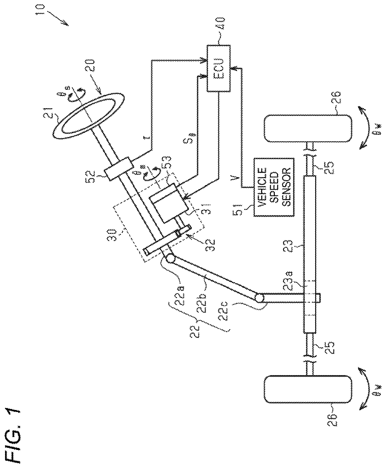
[0026]Hereinafter, a first embodiment will be described with an angle detection device embodied as an electronic control unit (ECU) of an electric power steering device (hereinafter, referred to as “EPS”).

[0027]As shown in FIG. 1, the EPS 10 includes a steering mechanism 20 that steers steered wheels 26, 26 based on steering operation of a driver, a steering assist mechanism 30 that assists the steering operation of the driver, and an electronic control circuit (ECU) 40 that controls operation of the steering assist mechanism 30.

[0028]The steering mechanism 20 includes a steering wheel 21 operated by the driver, and a steering shaft 22 that rotates integrally with the steering wheel 21. The steering shaft 22 includes a column shaft 22a connected to the steering wheel 21, an intermediate shaft 22b connected to a lower end portion of the column shaft 22a, and a pinion shaft 22c connected to a lower end portion of the intermediate shaft 22b. A lower end portion of the pinion shaft 22c ...

second embodiment

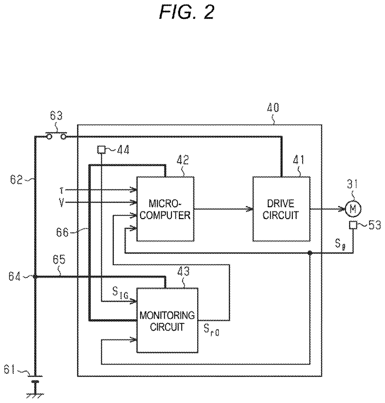
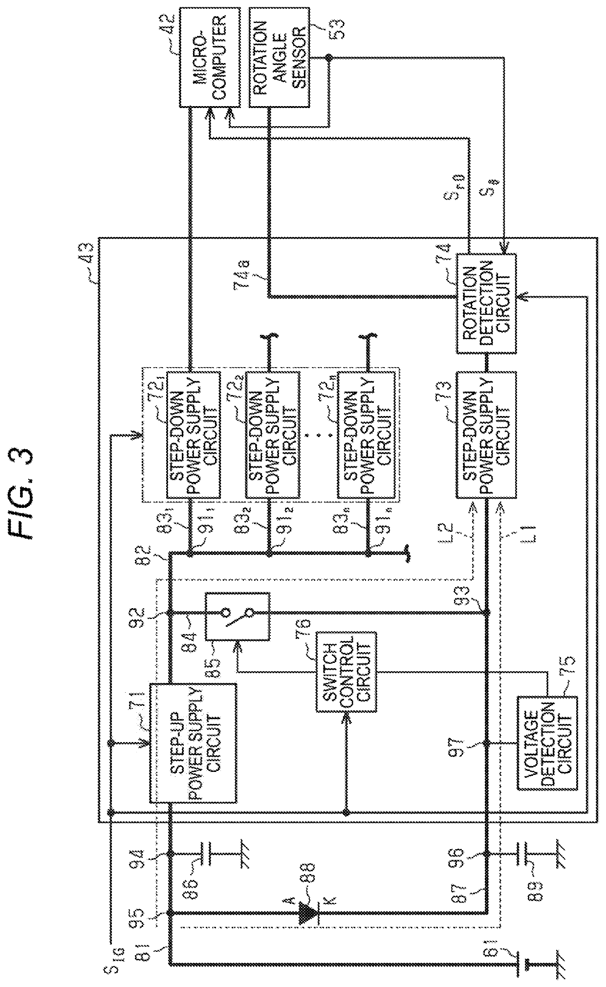
[0085]Next, a second embodiment of the rotation detection device will be described. This embodiment is different from the first embodiment in the configuration of the monitoring circuit 43.

[0086]As shown in FIG. 4, the feeder 84 is provided with a diode 101 instead of the previous switch 85. An anode (A) of the diode 101 is connected to the connection point 92 side, and a cathode (K) is connected to the connection point 93 side. The voltage detection circuit 75 and the switch control circuit 76 in the first embodiment are omitted.

[0087]Next, a function of the second embodiment will be described. Here, the power switch 63 is turned on.

[0088]First, in a case where the voltage of the DC power supply 61 is not lowered (in a case where “Vb≥Vth”), the voltage of the DC power supply 61 is higher than the voltage generated by the step-up / step-down power supply circuit 71. That is, a voltage at the connection point 93 on the anode side of the diode 88 is higher than a voltage at the connecti...


PUM


Abstract

A rotation detection device includes a rotation detection circuit, a step-up power supply circuit, a step-down power supply circuit, a first power supply path, and a second power supply path. The rotation detection circuit is configured to detect a rotation number of a motor that generates a torque applied to a steering mechanism of a vehicle, based on an electric signal. The electric signal is generated according to a rotation angle of the motor that is acquired through an in-vehicle sensor.

Description

CROSS REFERENCE TO RELATED APPLICATIONS[0001]This application claims priority from Japanese Patent Application No. 2018-184159 filed on Sep. 28, 2018, the entire contents of which are incorporated herein by reference.BACKGROUND OF THE INVENTIONField of the Invention[0002]The present invention relates to a rotation detection device.Description of Related Art[0003]In a related art, there is an electric power steering device for a vehicle (hereinafter, referred to as “EPS”) that generates an assist torque with a motor. An EPS control device controls the torque generated with the motor in accordance with a steering torque detected through a torque sensor. The control device energizes a coil of the motor in accordance with a rotation angle of the motor detected through a rotation angle sensor. Further, the control device calculates a steering angle, which is a rotation angle of a steering shaft, based on the rotation angle and a rotation number of the motor detected through the rotation ...

Claims


Application Information

Patent Timeline
IPC IPC(8): B62D5/04B62D1/16
CPCB62D1/16B62D5/0403B62D5/0409G01M17/06B62D15/0235B62D15/021B62D5/0481
Inventor KOZUKA, KENICHIODA, MASATOKAWAHARA, TADASHIOKI, MASASHI
Owner JTEKT CORP
Features
  • R&D
  • Intellectual Property
  • Life Sciences
  • Materials
  • Tech Scout
  • Unparalleled Data Quality
  • Higher Quality Content
  • 60% Fewer Hallucinations
Learn More