System and method for controlling flow of transmission fluid

Inactive Publication Date: 2020-04-09
GM GLOBAL TECH OPERATIONS LLC
View PDF0 Cites 0 Cited by
  • Summary
  • Abstract
  • Description
  • Claims
  • Application Information

AI Technical Summary

Benefits of technology

This patent is about a system and method for controlling the flow of transmission fluid in a vehicle. The system should be able to maintain pressure in the fluid system during a transition from fuel engine mode to electric vehicle mode and while driving on electricity. The method should also prevent a deadhead condition in the electric pump fluid sub-fluid system.

Problems solved by technology

With the fuel engine turned off, the mechanical pump is unable to supply pressure for the transmission fluid.
However, in transitioning from a fuel engine mode to an electric vehicle mode, pressure may be lost in the transmission fluid system due to the stoppage of the mechanical pump.
Line pressure fluctuations such as this can dramatically affect rotor speed of the electric pump.
Low cost sensors or sensorless motors have difficulty recovering from these speed fluctuations, especially if there is a deadhead condition in the electric pump fluid sub-system.
However, there are a small number of situations in which an increased pressurization and flow are required.
However, this is inefficient because the increased pump capacity is only needed for a small fraction of time, while a decreased pump capacity would be sufficient for most of the time the engine is operating.

Method used


Image

  • System and method for controlling flow of transmission fluid
  • System and method for controlling flow of transmission fluid
  • System and method for controlling flow of transmission fluid

Examples


Embodiment Construction

[0038]The following description is merely exemplary in nature and is not intended to limit the present disclosure, its application or uses.

[0039]It should be understood that throughout the drawings, corresponding reference numerals indicate like or corresponding parts and features. As used herein, the term module refers to processing circuitry that may include an application specific integrated circuit (ASIC), an electronic circuit, a processor (shared, dedicated, or group) and memory that executes one or more software or firmware programs, a combinational logic circuit, and / or other suitable components that provide the described functionality.

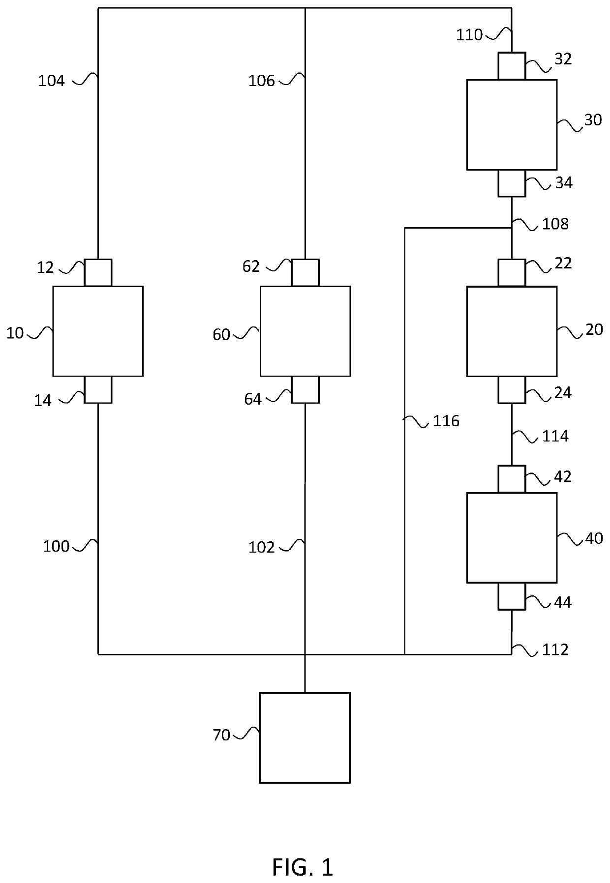
[0040]In accordance with an exemplary embodiment, FIG. 1 shows a system for controlling transmission fluid in a vehicle having a transmission 60. Transmission 60 may include transmission fluid intake 62 through which transmission fluid is supplied to transmission 60 and transmission fluid discharge 64 through which transmission fluid leaves tr...


PUM


Abstract

A system for controlling flow of transmission fluid in a vehicle may include a first pump, a second pump, a first check valve, a second check valve, and a fluid line. The first pump may include a first intake in fluid communication with a transmission discharge and a first discharge in fluid communication with a transmission intake. The second pump may include a second intake and a second discharge. The first check valve may include a first input in fluid communication with the second discharge and a first output in fluid communication with the transmission intake. The second check valve may include a second input in fluid communication with the transmission discharge and a second output in fluid communication with the second intake. The fluid line may include a first end in fluid communication with the second discharge and a second end in fluid communication with the second input.

Description

INTRODUCTION[0001]The subject disclosure relates to a system and method for controlling flow of transmission fluid in a vehicle.[0002]A traditional fuel engine vehicle may include a mechanical pump for supplying transmission fluid to a transmission. The mechanical pump may be powered by the engine. However, a parallel hybrid vehicle may operate in an electric vehicle mode in which the fuel engine is turned off. With the fuel engine turned off, the mechanical pump is unable to supply pressure for the transmission fluid. Thus, it may be necessary to provide an alternate system and method for pressurizing the transmission fluid. One possibility is to operate an auxiliary pump powered by the vehicle's electric bus.[0003]However, in transitioning from a fuel engine mode to an electric vehicle mode, pressure may be lost in the transmission fluid system due to the stoppage of the mechanical pump. Line pressure fluctuations such as this can dramatically affect rotor speed of the electric pu...

Claims


Application Information

Patent Timeline
IPC IPC(8): F16H61/02
CPCB60W10/11F16H61/061F16H61/0206F16H61/0009F16H61/0031F16H59/14F16H59/18F16H59/44F16H61/0025F16H2059/366
Inventor LI, DONGXULEE, CHUNHAO J.LAHR, DEREK F.BRUDER, DMITRIYSHIDORE, NEERAJ S.BUCKNOR, NORMAN K.SAMIE, FARZAD
Owner GM GLOBAL TECH OPERATIONS LLC
Why Eureka
Try Eureka