Touch-sensitive faucet and method for controlling same

a technology of touch-sensitive faucets and controls, applied in the field of faucets, can solve the problems of wasting water resources, complicated structure and higher cost, and inability to use faucets, and achieve the effects of preventing waste of water resources, simple operation, and simple structur

Inactive Publication Date: 2020-04-09
XIAMEN OLT SCI & TECH ELECTRONICS DEVING
View PDF0 Cites 0 Cited by
  • Summary
  • Abstract
  • Description
  • Claims
  • Application Information

AI Technical Summary

Benefits of technology

The invention is a touch-sensitive faucet that has the advantage of being able to output water through withdrawal, touch, and a manual switch. It has a simple structure and only requires a single water path to switch between the two functions. Turning the knob by 180 degrees is all it takes to complete the switching. Compared to directly outputting water through touch, the faucet uses an operating method that prevents water waste during operation and provides a better user experience.

Problems solved by technology

Such sensitive mode requires the use of a solenoid valve to control, but when the solenoid valve is damaged or powered off, faucets cannot be used.
To solve this problem, there is a kitchen faucet that combines a sensitive mode with a manual switch, wherein the switching between the sensitive mode and the manual switch is achieved by a switching valve body, but this requires an additional regulating valve to achieve the function of the manual switch, resulting in a complicated structure and higher cost.
In addition, the existing touch-sensitive faucets are basically turned on and off by touching faucet bodies for a predetermined time, but in practical use, if a user needs to turn the faucet and just touches the faucet and if an electrically charged object contacts the faucet, water will be directly discharged, resulting in waste of water resources.

Method used


Image

  • Touch-sensitive faucet and method for controlling same
  • Touch-sensitive faucet and method for controlling same
  • Touch-sensitive faucet and method for controlling same

Examples


Embodiment Construction

[0017]In order that the technical means, inventive features and workflow of the invention as well as the objects and efficacies achieved by the method of the invention are readily understood, the technical solutions in the embodiments of the invention will be clearly and completely described below in conjunction with the embodiments of the invention. It is apparent that the described embodiments are only part of rather than all of the embodiments in the invention. Based on the embodiments of the invention, all other embodiments obtained by the ordinary persons skilled in the art without inventive work belong to the protection scope of the invention.

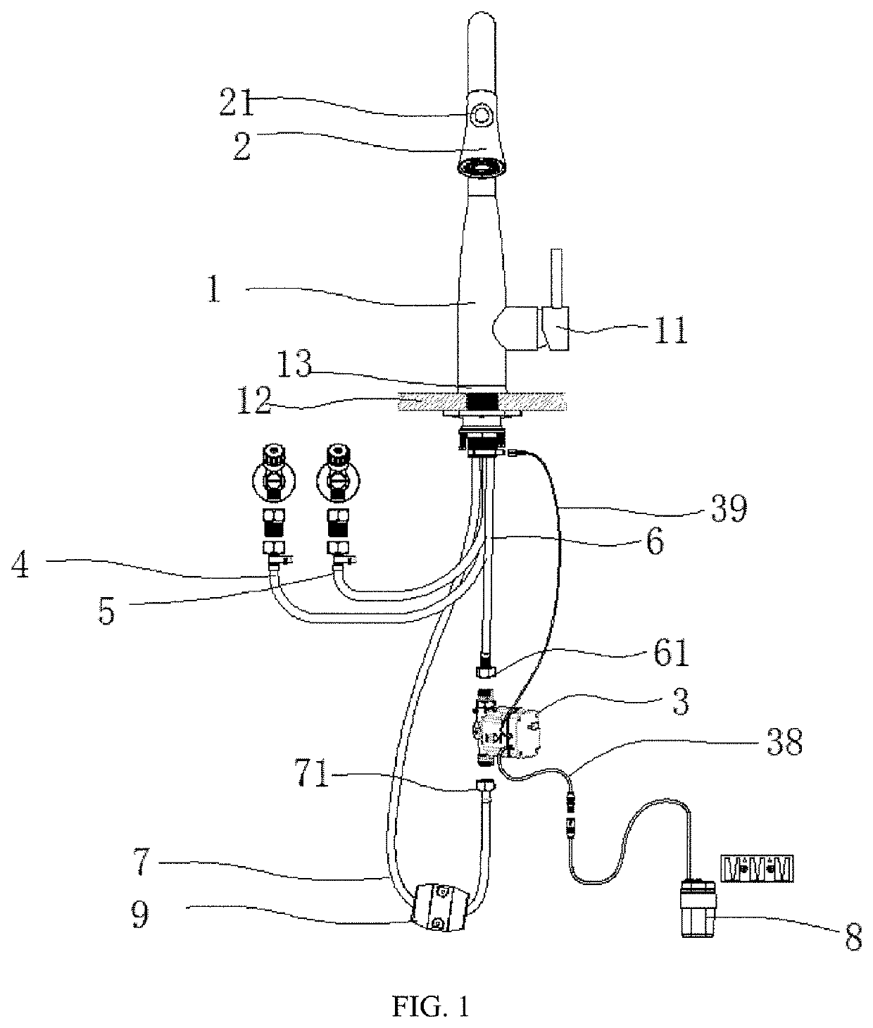
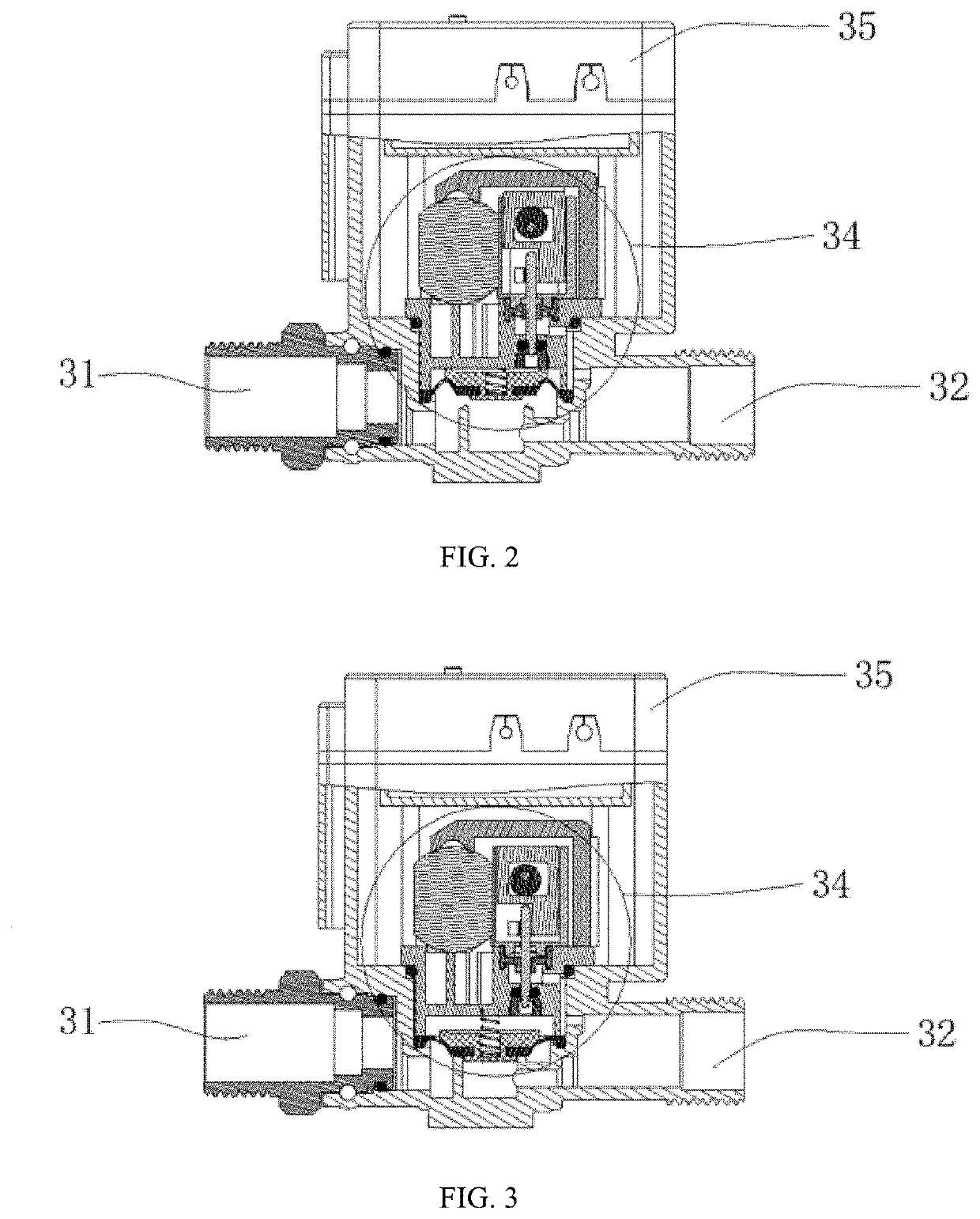
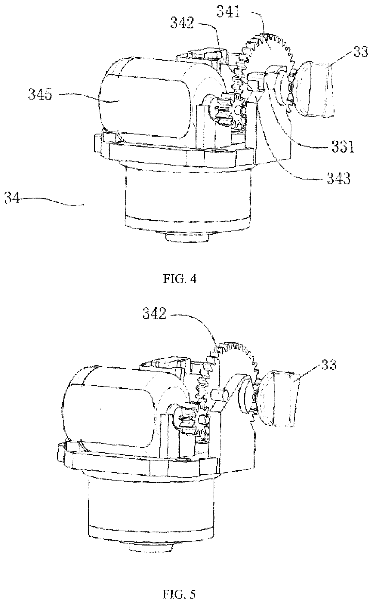
[0018]As shown in FIGS. 1 to 5, a touch-sensitive faucet comprises a faucet body 1, a spray head 2, a water mixing valve (not shown) and a master control box 3, wherein the spray head 2 is provided at an upper end of the faucet body 1, and the water mixing valve is provided in a lower end of the faucet body 1; a cold water intake end and ...


PUM


Abstract

The invention provides a touch-sensitive faucet, wherein a cold water intake end and a hot water intake end of a water mixing valve herein are respectively connected to a cold water intake pipe and a hot water intake pipe; and non-return valves are respectively provided between the cold water intake pipe and the water mixing valve and between the hot water intake pipe and the water mixing valve, preventing back flow due to pressure difference between cold water and hot water. The touch-sensitive faucet uses an operating method of outputting water after touch is removed, which can prevent waste of water resources caused by erroneous water output during operation and provide better user experience, compared with directly outputting water by touch.

Description

FIELD OF THE INVENTION[0001]The invention relates to the field of faucets, and particularly to a touch-sensitive faucet and a method for controlling same.BACKGROUND OF THE INVENTION[0002]As necessary devices for daily production and life, faucets are widely used in places such as kitchens and bathrooms. Early faucets were mainly turned on and off by manual switches. With the development of technology, water is turned on and off by a touch-sensitive mode. Such sensitive mode requires the use of a solenoid valve to control, but when the solenoid valve is damaged or powered off, faucets cannot be used. To solve this problem, there is a kitchen faucet that combines a sensitive mode with a manual switch, wherein the switching between the sensitive mode and the manual switch is achieved by a switching valve body, but this requires an additional regulating valve to achieve the function of the manual switch, resulting in a complicated structure and higher cost. In addition, the existing tou...

Claims


Application Information

Patent Timeline
IPC IPC(8): F16K31/60F16K31/05E03C1/23
CPCE03C2001/2311F16K31/605E03C1/2302F16K31/055F16K31/04F16K31/53F16K31/60E03C2001/0415E03C1/0412E03C1/0405E03C1/055F16K31/42F16K31/05
Inventor WU, DUANLONG
Owner XIAMEN OLT SCI & TECH ELECTRONICS DEVING
Why Eureka
Try Eureka