
Actuation device for ejecting at least one removable part of a missile, particularly a nose

a technology of a pyrotechnic actuator and a removable part, which is applied in the direction of weapons, projectiles, self-propelled projectiles, etc., can solve the problems of degrading the functioning of the pyrotechnic actuator, degrading the holding and performance of the structure, and triggering it unintentionally

Active Publication Date: 2020-04-09
MBDA FRANCE
View PDF0 Cites 3 Cited by
  • Summary
  • Abstract
  • Description
  • Claims
  • Application Information

AI Technical Summary

Benefits of technology

The present invention provides an actuation device for ejecting a removable part of a missile, such as a individual shell of a nose. The device includes a pyrotechnic actuator and at least one thermal insulation element to protect it from high temperatures. The actuator is also supported by retaining rods that are designed to withstand mechanical stresses during flight. The retaining rods are securely attached to the actuator and are broken into two parts at a weakening zone to separate the individual shells during ejection without causing debris damage. The second end of the retaining rod is also equipped with a threading for easy securing to a solid element of the missile. The technical effects of the invention include improved reliability, reduced mass and volume of the embedded actuation device, and minimized debris damage to the missile's performance.

Problems solved by technology

At these high speeds, the surface temperature of the missile can reach several hundred degrees Celsius under the effect of the aerothermal flow, which can be detrimental for the holding and the performance of the structures, electronic equipment and present sensors.
A solution could consist of using a pyrotechnic actuator such as a pyrotechnic ejector bolt, to generate the force necessary to separate the individual shells in very short times. However, the temperatures of several hundred degrees Celsius to which the individual shells are subjected, risk degrading the functioning of the pyrotechnic actuator secured to these, even trigger it unintentionally.
Furthermore, the products ejected and the blast effect of the pyrotechnic reaction are likely to damage the sensor of the terminal vehicle or to encumber its measuring capacity by depositing powder residues, for example.
This solution is therefore not applicable.

Method used


Image

  • Actuation device for ejecting at least one removable part of a missile, particularly a nose
  • Actuation device for ejecting at least one removable part of a missile, particularly a nose
  • Actuation device for ejecting at least one removable part of a missile, particularly a nose

Examples


Embodiment Construction

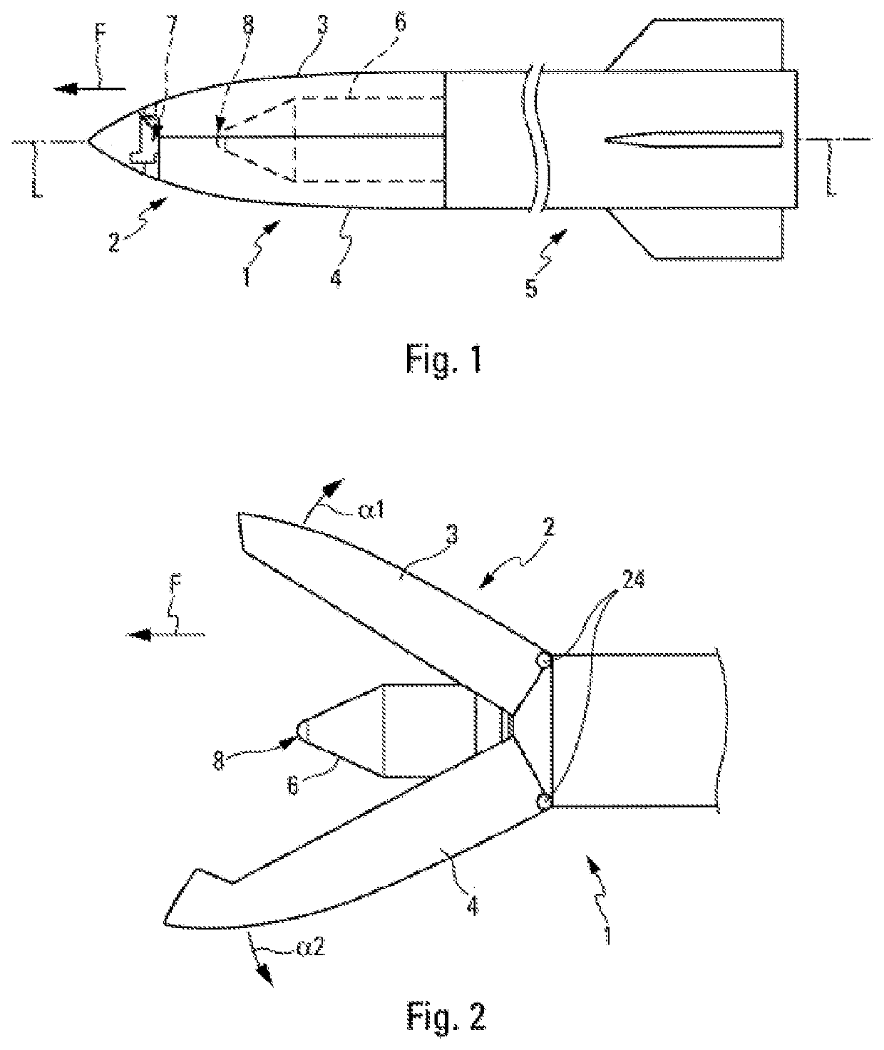
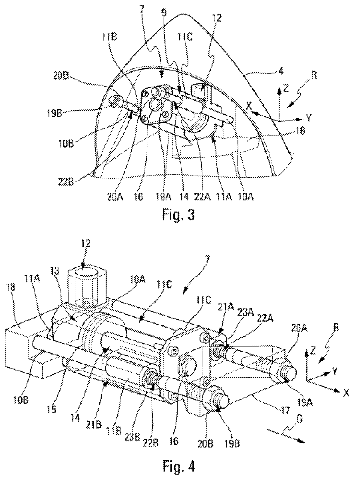
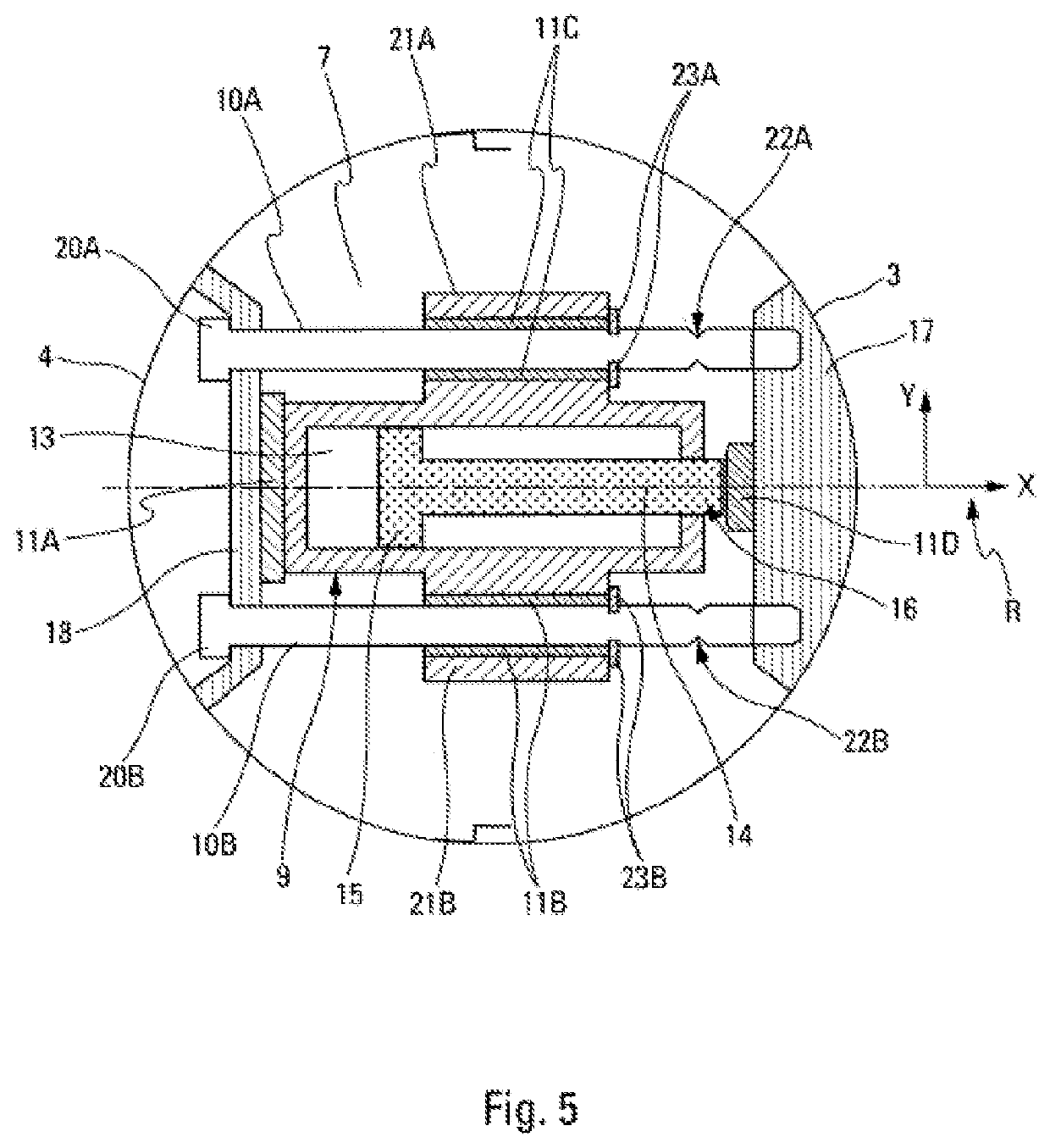
[0029]The present invention is applied to a missile 1 represented schematically in FIGS. 1 and 2, which is provided at the front (in the movement direction F of said missile 1) of a (protective) nose 2 comprising several removable parts, in this case, a plurality of shells 3, 4. The present invention concerns an actuation device 7 for the ejection of the nose 2. However, the present invention can be applied to any type of missile 1 comprising at least one removable part to be being ejected.

[0030]As represented in FIGS. 1 and 2, the missile 1 of longitudinal axis L-L, comprises at least one droppable propellant stage 5 and one terminal vehicle 6 which is arranged before this propellant stage 5.

[0031]Generally, such a flying terminal vehicle 6 comprises, in particular, at least one sensor 8 arranged upstream, for example forming part of a homing head and likely to be temperature-sensitive. The propellent stage 5 and the terminal vehicle 6 which can be of any usual type, are not furthe...


PUM


Abstract

An actuation device for ejecting a removable part of a missile includes a pyrotechnic actuator having a pyrotechnic charge configured to generate an overpressure and a piston configured to act on the removable part of the missile, at least one retaining rod, and at least one thermal insulation element configured to thermally insulate at least the pyrotechnic charge. The pyrotechnic actuator is configured to break the retaining rod.

Description

TECHNICAL FIELD[0001]The present invention concerns an actuation device making it possible to eject at least one removable part of a missile, and a missile provided with at least one such actuation device.STATE OF THE ART[0002]Although not exclusively, the present invention can be applied to a missile comprising at least one droppable propellant stage and one terminal vehicle which is arranged at the front of the propellant stage. Such a terminal vehicle generally comprises, in particular, a sensor for example forming part of a homing head and likely to be temperature-sensitive.[0003]More specifically, the present invention can be applied to a missile presenting a flying area remaining in the atmosphere and which has kinematic performance such as the terminal vehicle can be brought to hypersonic speeds. At these high speeds, the surface temperature of the missile can reach several hundred degrees Celsius under the effect of the aerothermal flow, which can be detrimental for the hold...

Claims


Application Information

Patent Timeline
IPC IPC(8): F42B15/36F42B15/34
CPCF42B15/36F42B15/34
Inventor QUERTELET, CLÉMENTLAHEYNE, CLYDE
Owner MBDA FRANCE
Learn More