Eureka AIR delivers breakthrough ideas for toughest innovation challenges, trusted by R&D personnel around the world.

Multilayer coil array

Pending Publication Date: 2020-04-09
MURATA MFG CO LTD
View PDF0 Cites 3 Cited by
  • Summary
  • Abstract
  • Description
  • Claims
  • Application Information

AI Technical Summary

Benefits of technology

The present patent is about a multilayer coil array that can prevent short circuits between adjacent coils and control the way they interact with each other. This is achieved by making the length of the coil conductor layer that contacts a non-magnetic layer different from the others. This design allows for better control over the coupling coefficient between coils. Overall, this patent provides a way to achieve better performance and efficiency in magnetic device design.

Problems solved by technology

In a multilayer coil array in which a plurality of coils are stacked inside an element body, there is a possibility of a short circuit occurring between adjacent coils.
However, there was a problem in that magnetic flux is interrupted if the upper end or the lower end of a coil contacts the non-magnetic layer.
On the other hand, although the interruption of magnetic flux can be suppressed when a magnetic layer is provided between the coil and the non-magnetic layer, there was a problem in that the plurality of coils can no longer magnetically couple with each other if the coil and the non-magnetic layer are completely separated from each other by the magnetic layer.

Method used


Image

  • Multilayer coil array
  • Multilayer coil array
  • Multilayer coil array

Examples


Embodiment Construction

[0032]Hereafter, a multilayer coil array according to an embodiment of the present disclosure will be described in detail while referring to the drawings. The embodiment described hereafter is for illustrative purposes and the present disclosure is not limited to the embodiment described hereafter. Unless specifically stated otherwise, it is not intended that scope of the present disclosure be limited to the dimensions, materials, shapes, relative arrangements, and so forth of constituent components described hereafter and these are merely explanatory examples. In addition, the sizes, shapes, positional relationships, and so forth of the constituent elements illustrated in the drawings may be exaggerated for the sake of clear explanation.

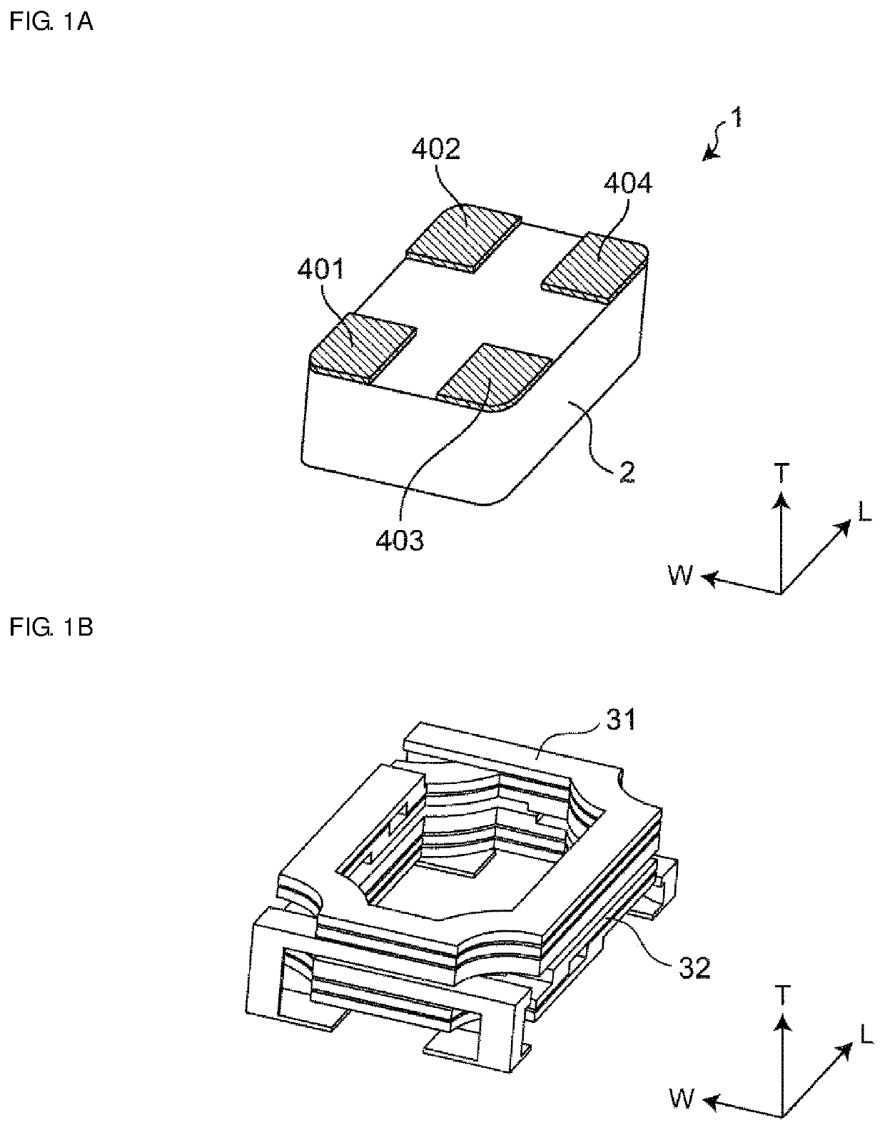
[0033]A multilayer coil array 1 according to an embodiment of the present disclosure is illustrated in FIGS. 1A and 1B. FIG. 1A is a perspective view in which the multilayer coil array 1 of the embodiment of the present disclosure is seem from the b...


PUM

PropertyMeasurementUnit
Lengthaaaaaaaaaa
Compositionaaaaaaaaaa
Magnetismaaaaaaaaaa

Abstract

A multilayer coil array includes an element body including a magnetic layer; first and second built-in coils; and first to fourth outer electrodes connected to the first and second coils. A non-magnetic layer is provided between the first and second coils. The first and second coils are each formed by a plurality of coil conductors being connected to each other. At least one out of a coil conductor of the first coil that is closest to the second coil among the plurality of coil conductors of the first coil and a coil conductor of the second coil that is closest to the first coil among the plurality of coil conductors of the second coil contacts the non-magnetic layer. The length of a coil conductor layer that contacts the non-magnetic layer of the coil conductor contacting the non-magnetic layer is different from the length of the other coil conductor layers.

Description

CROSS-REFERENCE TO RELATED APPLICATION[0001]This application claims benefit of priority to Japanese Patent Application No. 2018-190195, filed Oct. 5, 2018, the entire content of which is incorporated herein by reference.BACKGROUNDTechnical Field[0002]The present disclosure relates to a multilayer coil array.Background Art[0003]Japanese Unexamined Patent Application Publication No. 2016-186963 discloses a coil component of the related art. That is, Japanese Unexamined Patent Application Publication No. 2016-186963 discloses a multilayer electronic component in which magnetic layers and conductor patterns are stacked on top of one another and a coil is formed inside the resulting multilayer body by connecting the conductor patterns between the magnetic layers. The magnetic layers are formed of a metal magnetic material. At least one extending conductor pattern of the coil is connected to an outer terminal formed on a bottom surface of the multilayer body by a conductor formed at a cor...

Claims


Application Information

Patent Timeline
IPC IPC(8): H01F41/04H01F17/00H01F27/29H01F27/255H01F27/28H01F17/04C04B35/26
CPCH01F17/0013C04B2235/5436H01F17/04H01F27/292H01F27/255H01F27/2847C04B2235/5445C04B35/26H01F2017/0066C04B2235/3281H01F41/046H01F27/323H01F27/2804H01F2027/2809H01F41/043C04B35/265C04B2235/3284
Inventor SATO, MITSUHIROKAWABATA, RYOHEI
Owner MURATA MFG CO LTD
Why Eureka
Eureka Blog
Learn More