Supercharge Your Innovation With Domain-Expert AI Agents!

Method for Detecting Errors in a Rotating Position Sensor System Having Sine and Cosine Signals

a technology of rotational position and sensor system, applied in the field of position sensors, can solve problems such as system failure, deviation of two sensor output signals,

Active Publication Date: 2020-04-16
INTEGRATED DEVICE TECH INC
View PDF0 Cites 10 Cited by
  • Summary
  • Abstract
  • Description
  • Claims
  • Application Information

AI Technical Summary

Benefits of technology

The patent describes a method to correct errors in a rotational position sensor that produces sine and cosine signals. The method involves collecting data from both signals over the rotation of a motor shaft, determining parameters to account for offsets and amplitude differences, and then using those parameters to correct the signals. The result is a more accurate and reliable measurement of position.

Problems solved by technology

However, these systems exhibit inaccuracies and are then calibrated to account for these inaccuracies.
However, for cost and handling reasons, this method can be used only for product development and during the end-of-line calibration in a production line, but is not generally used on every unit produced during normal operation.
A deviation of the two sensor output signals is considered a failure of the system, but it might not reveal which sensor is defective and which one is operating correctly.
Particularly in high speed sensor systems, as for example in a rotor position sensor of an electric motor, the sensor signal cannot be interrupted during operation, therefore it is not allowed, for example, to replace the sensor raw signal with a known reference signal for making a reference measurement.

Method used


Image

  • Method for Detecting Errors in a Rotating Position Sensor System Having Sine and Cosine Signals
  • Method for Detecting Errors in a Rotating Position Sensor System Having Sine and Cosine Signals
  • Method for Detecting Errors in a Rotating Position Sensor System Having Sine and Cosine Signals

Examples


Embodiment Construction

[0030]In the following description, specific details are set forth describing some embodiments of the present invention. It will be apparent, however, to one skilled in the art that some embodiments may be practiced without some or all of these specific details. The specific embodiments disclosed herein are meant to be illustrative but not limiting. One skilled in the art may realize other elements that, although not specifically described here, are within the scope and the spirit of this disclosure.

[0031]This description illustrates inventive aspects and embodiments should not be taken as limiting—the claims define the protected invention. Various changes may be made without departing from the spirit and scope of this description and the claims. In some instances, well-known structures and techniques have not been shown or described in detail in order not to obscure the invention.

[0032]Some embodiments of this invention provide a simple method is described, which allows precise err...


PUM


Abstract

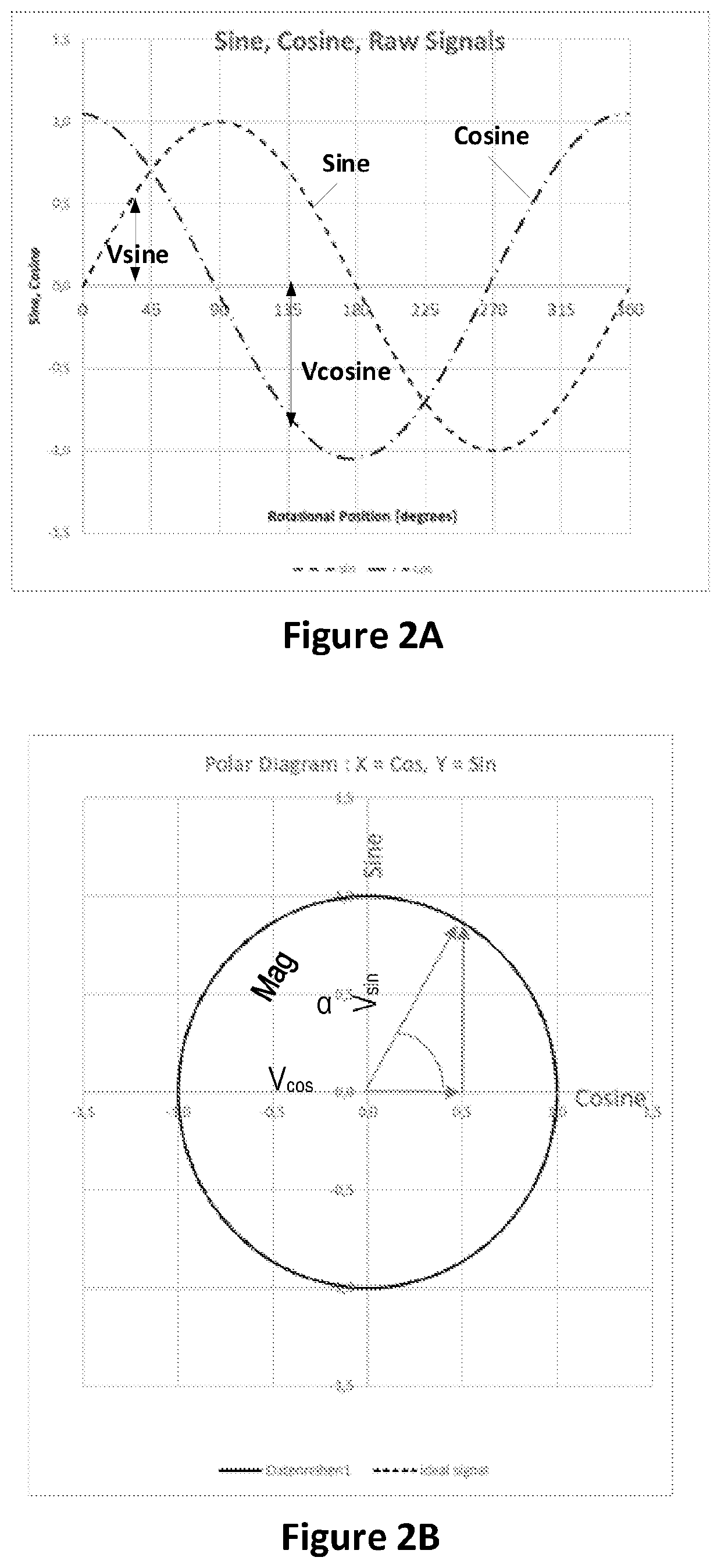
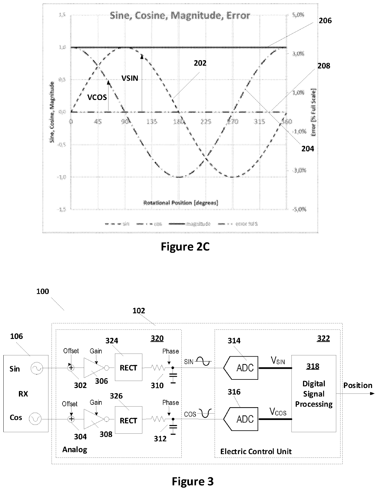
In some embodiments, a method of correcting for errors in a rotational position sensor having a sine signal and a cosine signal is presented. The method includes compiling data from the sine signal and the cosine signal over a period of rotation of a motor shaft; determining offset correction parameters from the data; correcting the data with the offset correction parameters; determining amplitude difference parameters from the data; correcting the data with the amplitude difference parameters; determining phase difference parameters from the data; correcting the data with the phase difference parameters; and using the offset correction parameters, the amplitude difference parameters, and the phase difference parameters to correct the sine signal and the cosine signal.

Description

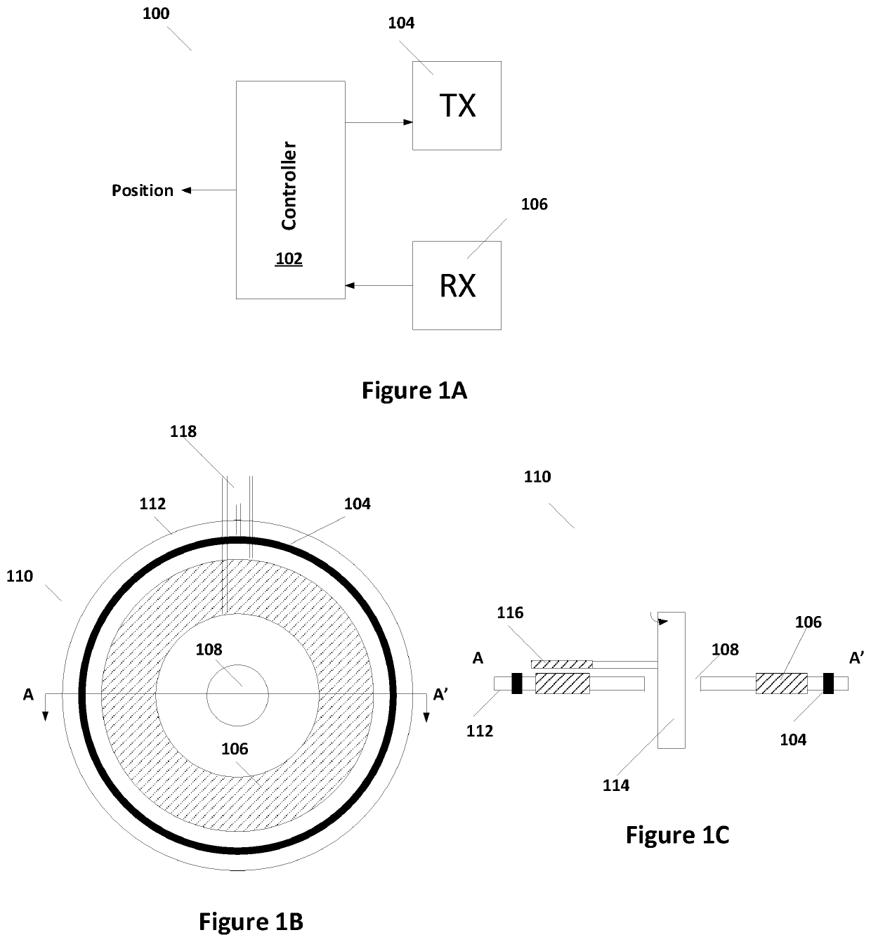
RELATED APPLICATION[0001]This disclosure claims priority to U.S. Provisional Application Ser. No. 62 / 745,936, filed on Oct. 15, 2018, which is herein incorporated by reference in its entirety.TECHNICAL FIELD[0002]Embodiments of the present invention are related to position sensors and, in particular, to a method for detecting errors in a rotational position sensor system having sine and cosine signals.DISCUSSION OF RELATED ART[0003]Position sensors are used in various settings for measuring the position of one component with respect to another. Inductive position sensors can be used in automotive, industrial and consumer applications for absolute rotary and linear motion sensing. In many inductive positioning sensing systems, a transmitter coil is driven to induce eddy currents in a metallic target that is sliding or rotating above a set of receiver coils. Receiver coils receive the magnetic field generated from eddy currents and the transmitter coils and provide signals to a proces...

Claims


Application Information

Patent Timeline
IPC IPC(8): G01D5/244
CPCG01D5/2448G01D5/2053G01D3/036
Inventor JANISCH, JOSEFMUESCH, ERHARD
Owner INTEGRATED DEVICE TECH INC
Features
  • R&D
  • Intellectual Property
  • Life Sciences
  • Materials
  • Tech Scout
  • Unparalleled Data Quality
  • Higher Quality Content
  • 60% Fewer Hallucinations
Learn More