Eureka AIR delivers breakthrough ideas for toughest innovation challenges, trusted by R&D personnel around the world.

Holding member, work molding system, and work molding method

Pending Publication Date: 2020-04-23
DAI NIPPON PRINTING CO LTD
View PDF2 Cites 0 Cited by
  • Summary
  • Abstract
  • Description
  • Claims
  • Application Information

AI Technical Summary

Benefits of technology

The present invention provides a work holding mechanism, a work molding system, and a work holding method that can hold a work by adsorbing it to a body part with a three-dimensional shape. This reduces the amount of work used in the system. Additionally, the invention allows for the heating and molding of a next formed work while it is still in a previous molding state, which speeds up the overall processing time. The molding device can perform vacuum molding and resin injection molding on the formed work.

Problems solved by technology

Since the work having a flat shape extending straight downward is molded using molds as described above, the holding hand of the work molding system disclosed in JP 5866398 B2 is problematic in that it is difficult to reduce the amount of usage of the work in the work molding system.
However, the problem is that a work holding mechanism capable of holding a work in a curved state in such a manner has not been available hitherto.
Since the processes for producing a molded article are performed in order in the conventional injection molding system, there is a problem that any delay in each of the processes directly affects the delay of the production time of the molded article in the case of producing a molded article which requires a long time for, for example, heating and injection-molding a sheet-like film.
Accordingly, a plurality of robots such as a robot for supplying the film to the injection molding machine and a robot for conveying a molded article need to be introduced, resulting in a problem in that the overall configuration of the system becomes complicated.
Therefore, in the case of a thin sheet-like film, there is a problem that the film may undergo wrinkling, warping or the like when heated.
Furthermore, a sheet-like film that has undergone wrinkling, warping or the like cannot be sufficiently adsorbed to the molds during vacuum molding, so that the sheet-like film cannot be brought into close contact with the molds, resulting in a problem in that the design quality of the molded article is reduced.
Since a robot hand is installed inside the injection molding device in the injection molding system disclosed in JP 5926352 B2, the movable range of the robot hand is narrow, resulting in a problem in that the robot hand may in some cases interfere with the constituent members of the injection molding machine.

Method used


Image

  • Holding member, work molding system, and work molding method
  • Holding member, work molding system, and work molding method
  • Holding member, work molding system, and work molding method

Examples


Embodiment Construction

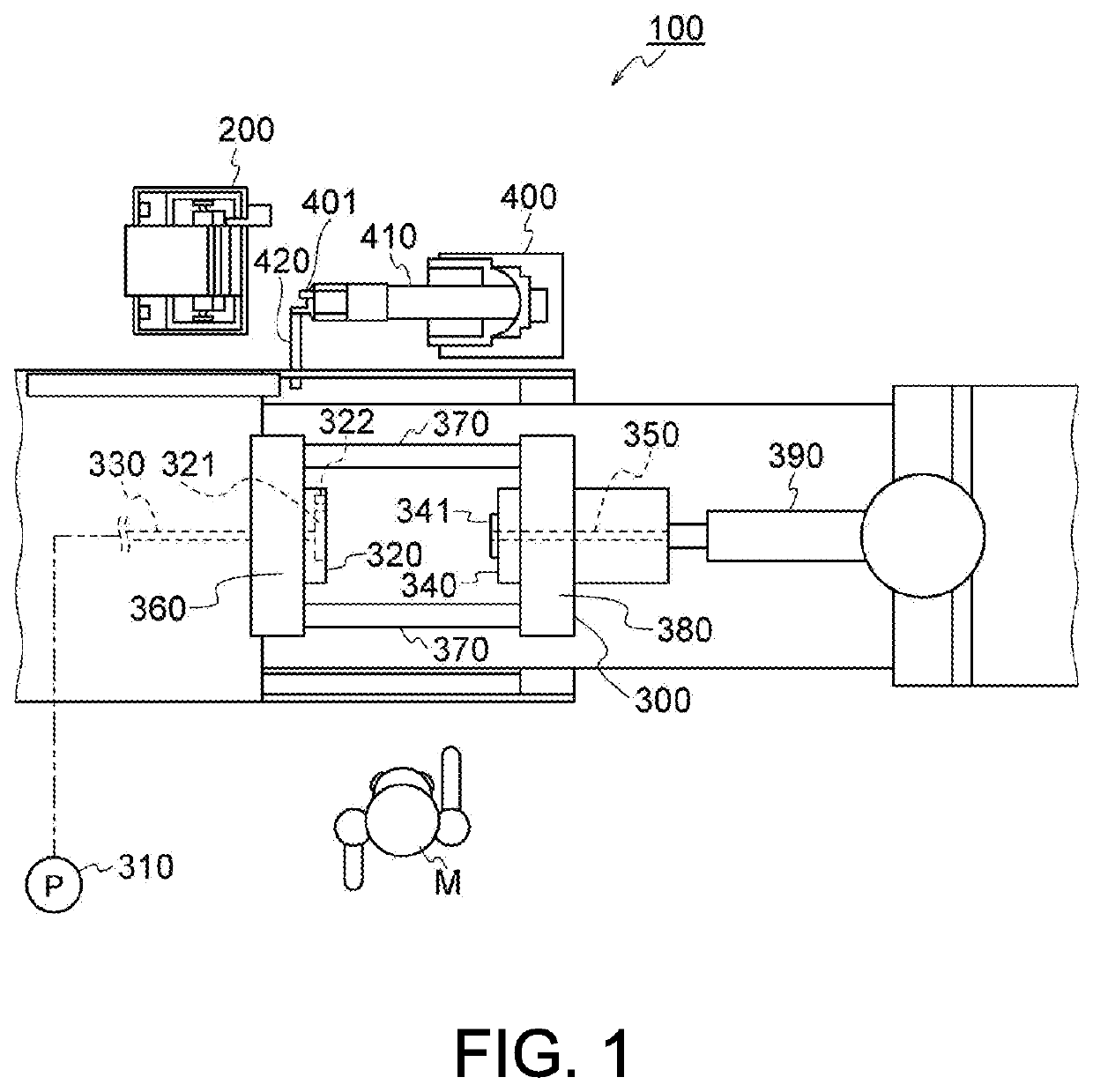
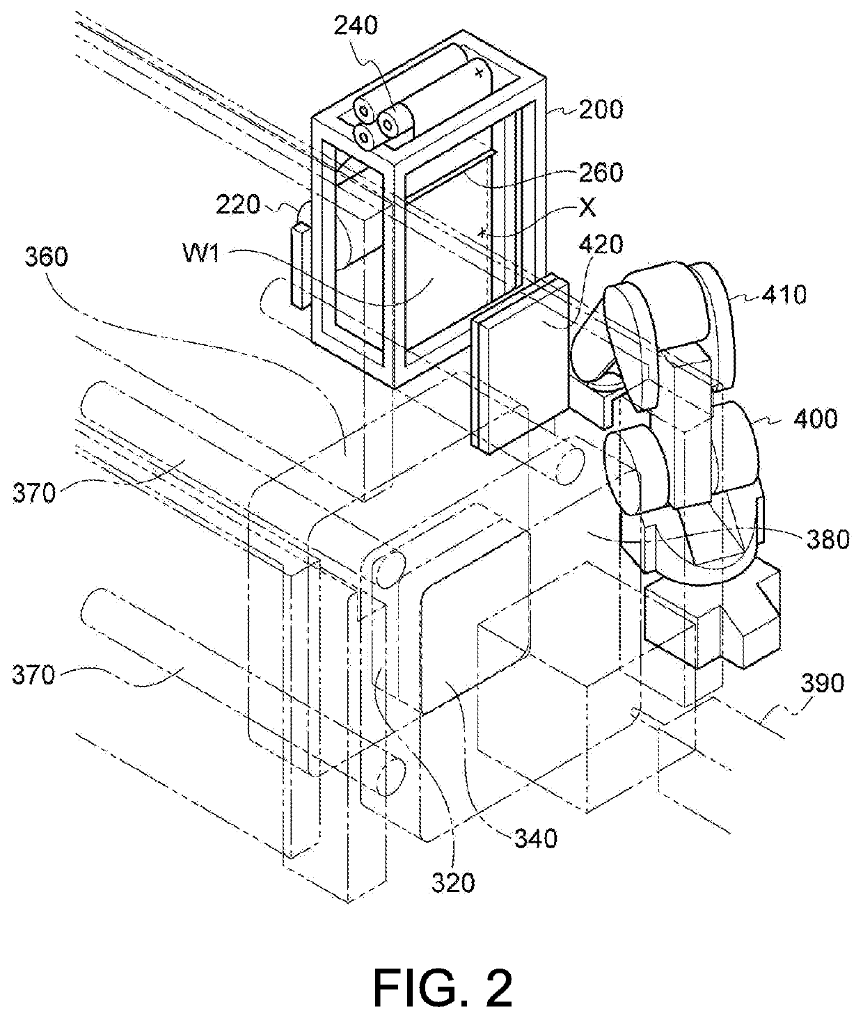
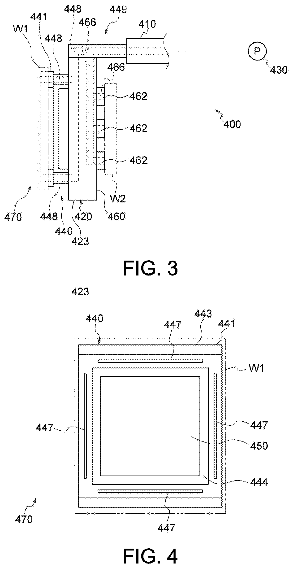
[0064]Hereinafter, an embodiment of the present invention will be described with reference to the drawings. FIGS. 1 to 21 are diagrams showing a work molding system according to the present embodiment, and a work molding method using such a work molding system. It is noted that in FIG. 1, an operator performing operations in the work molding system according to the present embodiment is indicated by reference character M. In FIG. 2, a positioning mark provided on an original film roll is indicated by reference character X. In FIGS. 2 to 4, 6 to 8, 10 to 13, and 15 to 21, a formed work before being molded by a molding device is indicated by reference character W1, and a molded article produced as a result of the formed work being molded by the molding device is indicated by reference character W2. In FIGS. 7, 15, and 16, a formed work held by a conventional work holding mechanism is indicated by reference character W.

[0065]First, a work molding system 100 according to the present emb...


PUM

PropertyMeasurementUnit
Shapeaaaaaaaaaa

Abstract

A work holding mechanism includes a body part having a three-dimensional shape including at least a recess or a protrusion, and an adsorption part for holding a work by adsorbing the work onto the body part in conformity to the three-dimensional shape of the recess or the protrusion provided in the body part. The work is held by being adsorbed in conformity to the three-dimensional shape of the body part, and, therefore, the amount of usage of the work in a work molding system can be reduced as compared with when the work is held so as to have a flat shape.

Description

TECHNICAL FIELD[0001]The present invention relates to a work holding mechanism for holding a work in a work molding system that molds a work and the work molding system, as well as a work holding method using such a work holding mechanism. The present invention also relates to a work molding system for producing a molded article by molding a formed work formed by a work forming device, a conveying device for conveying the formed work and a molded article produced by molding the formed work, a holding member provided in such a conveying device, and a work molding method using such a work molding system.BACKGROUND ART[0002]Conventionally, in a work molding system for producing a molded article by molding a work (e.g., a film) using an injection molding machine or the like, the following processes are performed in order, step by step. More specifically, the process of feeding out a film from an original film roll, the process of cutting the fed out film into a sheet form, the process o...

Claims


Application Information

Patent Timeline
IPC IPC(8): B29C45/42B29C45/17
CPCB29C45/42B29C45/1761B29C45/14008B29C45/1418B29C2045/14286B29C45/76B29C2945/00B29C2945/76083B29C2945/76294B29C2945/76357B29C2945/76464B29C2945/76568B29C2945/76795B29C2945/76809B29C2045/425B29C45/762
Inventor ISHIZUKA, KOHEIUEMATSU, TAISUKEKONNO, TAKASHIATAKE, HIROYUKIMEIKI, YOSHIYUKIARIYAMA, MINORUIDEGAMI, MASATO
Owner DAI NIPPON PRINTING CO LTD
Why Eureka
Eureka Blog
Learn More