
Excavator bucket & manufacturing method

a technology for excavators and buckets, applied in mechanical machines/dredgers, soil shifting machines/dredgers, construction, etc., can solve the problems of prolonging the working life of the bucket, forming a heat-affected zone (haz), and exposing the buckets to a high degree of abrasive wear

Active Publication Date: 2020-04-23
SSAB TECH
View PDF6 Cites 2 Cited by
  • Summary
  • Abstract
  • Description
  • Claims
  • Application Information

AI Technical Summary

Benefits of technology

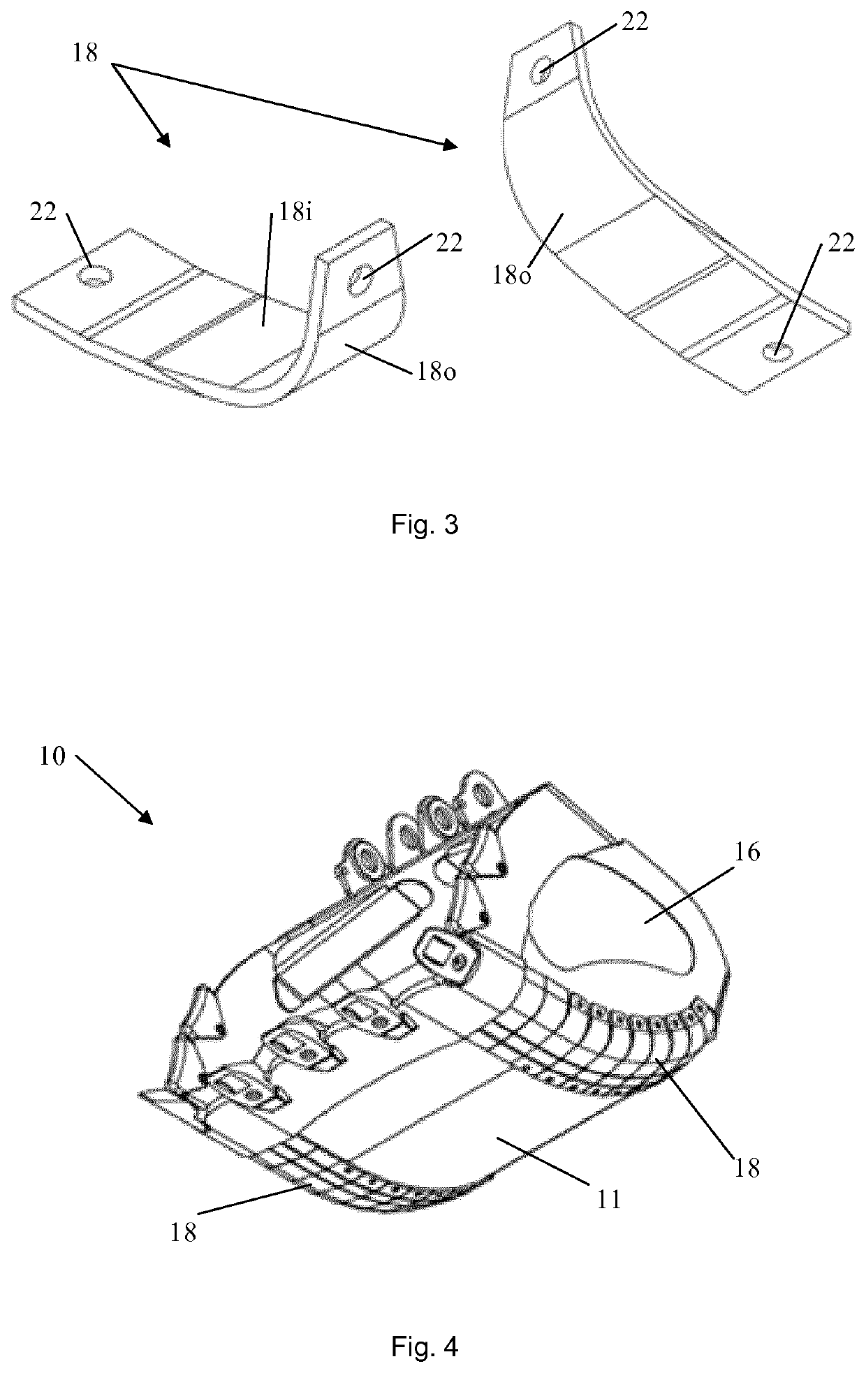
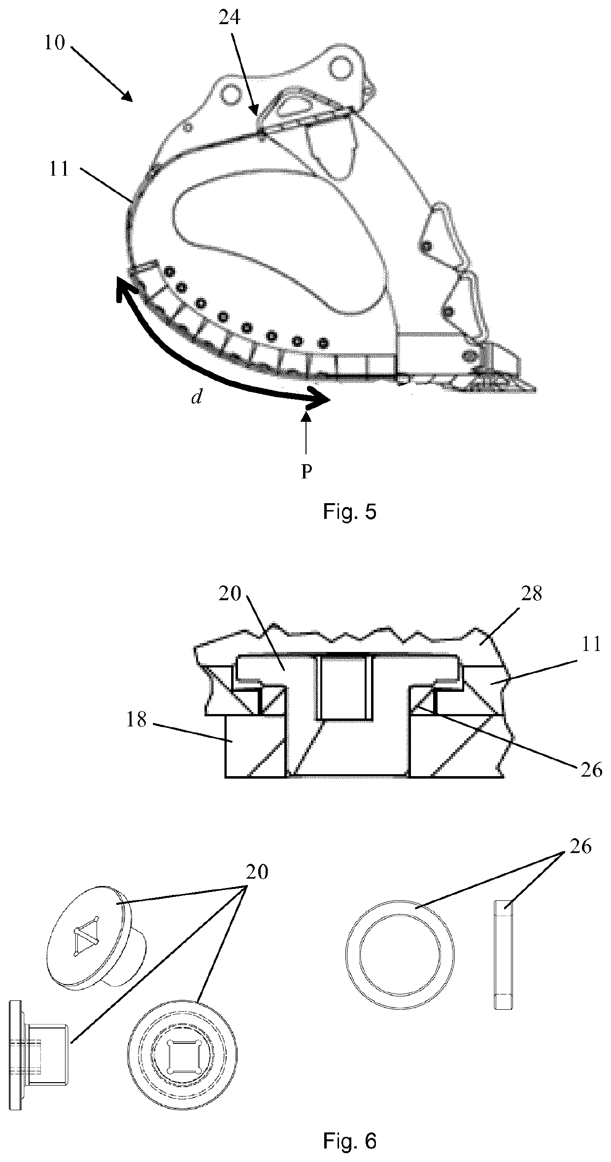
The invention relates to a bucket design that allows for easy disconnection of the floor and side wall without the need for excessive force. Additionally, the floor is not welded to the side wall, which prevents the formation of a heat-affected zone that could compromise the physical properties of the material. This design ensures that the bucket remains strong and the wear component maintains its physical properties.

Problems solved by technology

Such buckets are exposed to a high degree of abrasive wear and it is known to mount wear components (also known as heel segments, heel blocks, cast heels, corners, corner guards, corner shrouds, wear strips or wear plates) on the outer surface of the bucket around the connection between the floor and a side wall of the bucket which forms a bucket corner edge.
The wear components provide additional strengthening and abrasion resistance at the bucket corner edges and thereby prolong the working life of the bucket.
Wear resistant steel is often used to manufacture a excavator bucket and the welding and heat-intensive cutting operations that are used when manufacturing the bucket may result in the formation of a heat-affected zone (HAZ), which is the area of base material that is not melted and that has had its microstructure and properties altered by the welding or cutting operations.
The heat from a welding and / or cutting process and subsequent re-cooling may thereby adversely affect the steel around the weld interface and consequently weaken the bucket in the area of the bucket corner edges.
Furthermore, since buckets for earth-working or materials-handling machines are usually quite large and heavy, moving and supporting bucket parts, such as the floor and the side walls of the bucket, while they are being welded together can make the manufacturing process and repair or maintenance work quite complex and time consuming.

Method used


Image

  • Excavator bucket & manufacturing method
  • Excavator bucket & manufacturing method
  • Excavator bucket & manufacturing method

Examples


Embodiment Construction

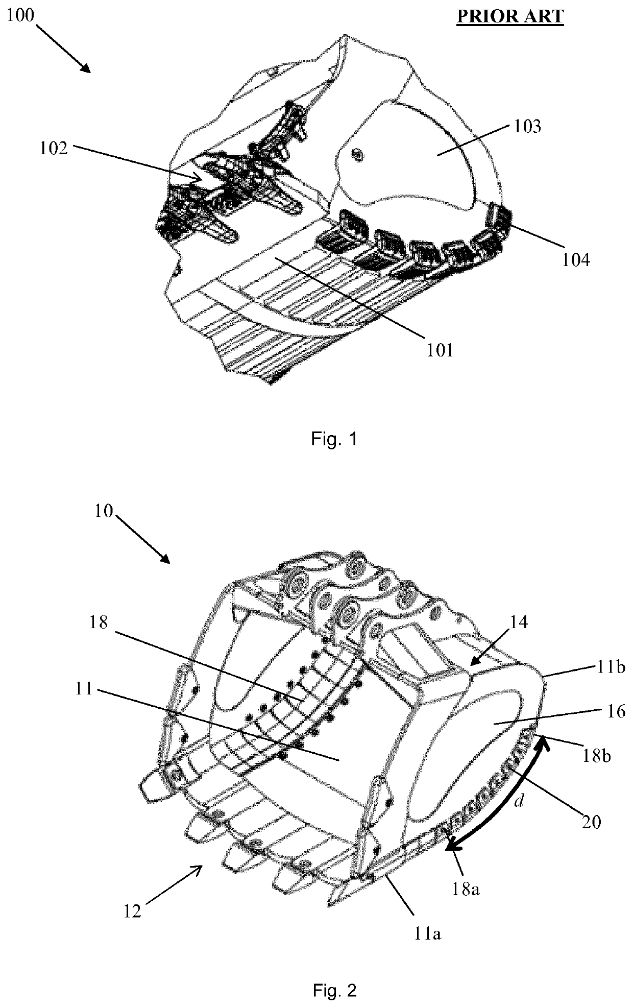
[0045]FIG. 1 shows a perspective view of a steel bucket 100 according to the prior art viewed at angle from below. The prior art bucket 100 has a floor 101 that extends from a front cutting edge 102 of the bucket 100 up to a top assembly (not shown) that connects the prior art bucket 100 to an earth-moving or materials-handling machine. The prior art bucket 100 also comprises a side wall 103, an edge of which is welded to an edge of the floor 101 of the prior art bucket 100 along the entire length of the floor 101 of the bucket to form a non-disconnectable and non-replaceable bucket corner edge. The prior art bucket 100 also comprises a plurality of spaced apart wear components that have been welded to outside of the prior art bucket 100 across the weld joint connecting the floor 101 of the prior art bucket to its side wall 103.

[0046]In order to remove and replace one of the wear components 104 of the prior art bucket 100, the wear component 104 must be cut off the prior art bucket ...


PUM


Abstract

Bucket for an earth-working or materials-handling machine, which comprises a floor and a side wall, and at least one wear component that is removably attached to the floor and the side wall by means of at least one mechanical fastener. The floor and the side wall are disconnectably connected to each other via the at least one wear component so as to form a replaceable bucket corner edge along at least a part of the floor and the side wall.

Description

TECHNICAL FIELD[0001]The embodiments described herein concern a bucket for an earth-working or materials-handling machine, and a method for manufacturing such a bucket.BACKGROUND OF THE INVENTION[0002]Earth-working or materials-handling machines, such as excavators, are widely used in the construction and mining industries to move material, such as earth, sand, rocks and snow. In many of these applications, buckets are used to pick up and transport material and for example load it onto a truck or move it to a different location. Such buckets are exposed to a high degree of abrasive wear and it is known to mount wear components (also known as heel segments, heel blocks, cast heels, corners, corner guards, corner shrouds, wear strips or wear plates) on the outer surface of the bucket around the connection between the floor and a side wall of the bucket which forms a bucket corner edge. The wear components provide additional strengthening and abrasion resistance at the bucket corner ed...

Claims


Application Information

Patent Timeline
Patent Type & Authority Applications(United States)
IPC IPC(8): E02F3/40E02F9/28
CPCE02F3/401E02F9/2883E02F3/40E02F9/28
Inventor COULSON, BRIAN
Owner SSAB TECH
Learn More