Method of and system for performing subsurface imaging using vibration sensing

a technology of vibration sensing and subsurface imaging, applied in the direction of scanning probe techniques, instruments, using reradiation, etc., can solve the problems of poor detection, high cost of depth resolution, and significantly more complex interpretation of images, so as to prevent overheating and subsequent thermal damage of the transducer, the effect of increasing the operation voltag

Pending Publication Date: 2020-04-23
NEDERLANDSE ORG VOOR TOEGEPAST-NATUURWETENSCHAPPELIJK ONDERZOEK (TNO)
View PDF4 Cites 1 Cited by
  • Summary
  • Abstract
  • Description
  • Claims
  • Application Information

AI Technical Summary

Benefits of technology

[0010]Preferably, in accordance with some embodiments, the discontinuous signal applied is a pulse signal. The pulse signal or pulse train applied must be short enough to ensure that the forward and backward propagation of the discontinuous signal in the sample do not mix. A continuous wave excitation would in fact lead to a strongly non-uniform sample surface displacement, making the interpretation of the images significantly more complex than in the case of pulsed excitation. Ultimately, pulse signals having a duration longer than the acoustic travel time through the sample are to be avoided. A discontinuous and short pulse prevents transducer overheating and subsequent thermal damages at higher operation voltages compared to continuous wave excitation. When the duration becomes too long, this will go at the cost of depth resolution, resulting in poor detection. The spatial pulse length may thus be dependent on the material (as the sound velocity for different materials is different), and may be shorter for softer materials while being longer for harder materials. In some embodiments, the discontinuous signal has a signal time duration shorter than the acoustic travel time to the desired depth of detection. For example, for a depth of 300 micrometer in a sample made primarily of a material having a sound velocity of 5000 meters per second, the pulse duration preferably does not exceed (300*10−6) / 5000=6*10−8 sec (60 nanoseconds). It is further noted that, if not only the presence of a subsurface feature is to be detected, but it is also desired to measure it's thickness, then the pulse duration must be smaller than the expected travel time through the subsurface feature.

Problems solved by technology

A continuous wave excitation would in fact lead to a strongly non-uniform sample surface displacement, making the interpretation of the images significantly more complex than in the case of pulsed excitation.
When the duration becomes too long, this will go at the cost of depth resolution, resulting in poor detection.

Method used


Image

  • Method of and system for performing subsurface imaging using vibration sensing
  • Method of and system for performing subsurface imaging using vibration sensing
  • Method of and system for performing subsurface imaging using vibration sensing

Examples


Embodiment Construction

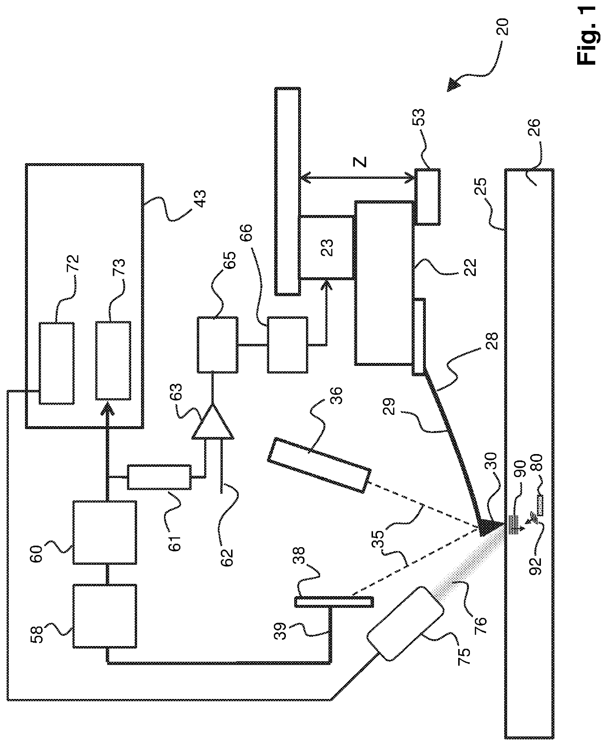
[0020]FIG. 1 schematically illustrates a measurement system 20 in accordance with an embodiment of the invention. The system 20 may be applied for performing a method in accordance with the present invention, for example the method in accordance with the embodiment illustrated in FIG. 3 amongst others. In the system 20, a probe 28 is attached to a scan head 22. The scan head 22 enables scanning of the probe 28 relative to the surface 25 of a sample 26. The probe 28 consists of a cantilever 29 and a probe tip 30. During scanning, the probe tip 30 is brought in contact with the surface 25 of the sample 26. For example the probe tip 30 may be scanned across the surface 25 of the sample 26 in contact mode (continuous contact between the probe tip 30 and the surface 25 of the sample 26). A laser unit 36 provides a collimated laser beam 35 that impinges on the cantilever 29 and reflects towards an optical detector 38 (e.g. photo diode). Using the optical detector 38, vibrations in the can...


PUM

PropertyMeasurementUnit
frequencyaaaaaaaaaa
depthsaaaaaaaaaa
frequencyaaaaaaaaaa

Abstract

The present invention relates to a method of performing subsurface imaging of embedded structures in a substrate underneath a substrate surface, the method comprising the steps of applying, using a signal application actuator, an acoustic input signal to the substrate, detecting, using a vibration sensor, a return signal from the substrate and analyzing the return signal for obtaining information on the embedded structures, for enabling imaging thereof wherein the step of applying the acoustic input signal comprises applying a discontinuous signal of an acoustic signal component to the substrate, the acoustic signal component having a frequency above 1 gigahertz, such that the return signal includes a scattered fraction of the discontinuous signal scattered from the embedded structures. The invention further relates to a system.

Description

FIELD OF THE INVENTION[0001]The present invention is directed at a method of performing subsurface imaging of embedded structures in a substrate underneath a substrate surface, the method comprising the steps of: applying, using a signal application actuator, an acoustic input signal to the substrate; detecting, using a vibration sensor, a return signal from the substrate; and analyzing the return signal for obtaining information on the embedded structures, for enabling the imaging thereof.[0002]The invention is further directed at a system for performing subsurface imaging of embedded structures in a substrate underneath a substrate surface, the system comprising a signal application actuator for applying an acoustic input signal to the substrate, a vibration sensor for detecting a return signal from the substrate, and an analyzer for analyzing the return signal, for obtaining information on the embedded structures for enabling imaging thereof.BACKGROUND[0003]Developments in the se...

Claims


Application Information

Patent Timeline
Patent Type & Authority Applications(United States)
IPC IPC(8): G01N29/06G01N29/24G01N29/26G01S15/89G01S15/04G01S7/527
CPCG01N29/2437G01S7/527G01N29/26G01N29/0654G01S15/89G01S15/04G01Q60/32G01N29/2418G01N29/343G01N2291/044G01N29/069
Inventor PIRAS, DANIELEVAN NEER, PAUL LOUIS MARIA JOSEPHVAN ES, MAARTEN HUBERTUSSADEGHIAN MARNANI, HAMED
Owner NEDERLANDSE ORG VOOR TOEGEPAST-NATUURWETENSCHAPPELIJK ONDERZOEK (TNO)
Why Eureka
Try Eureka