Method for observing a sample

a sample and observing technology, applied in the field of sample observation, can solve the problem that algorithms may induce reconstruction noise in the reconstructed imag

Active Publication Date: 2020-04-23
COMMISSARIAT A LENERGIE ATOMIQUE ET AUX ENERGIES ALTERNATIVES
View PDF0 Cites 7 Cited by
  • Summary
  • Abstract
  • Description
  • Claims
  • Application Information

AI Technical Summary

Benefits of technology

[0038]Other advantages and features will become more clearly apparent from the following description of particular embodiments of the invention, which are given by way of nonlimiting example, and shown in the figures listed below.

Problems solved by technology

However, holographic reconstruction algorithms may induce reconstruction noise in the reconstructed image, which noise is referred to as “twin images”.

Method used


Image

  • Method for observing a sample
  • Method for observing a sample
  • Method for observing a sample

Examples


example

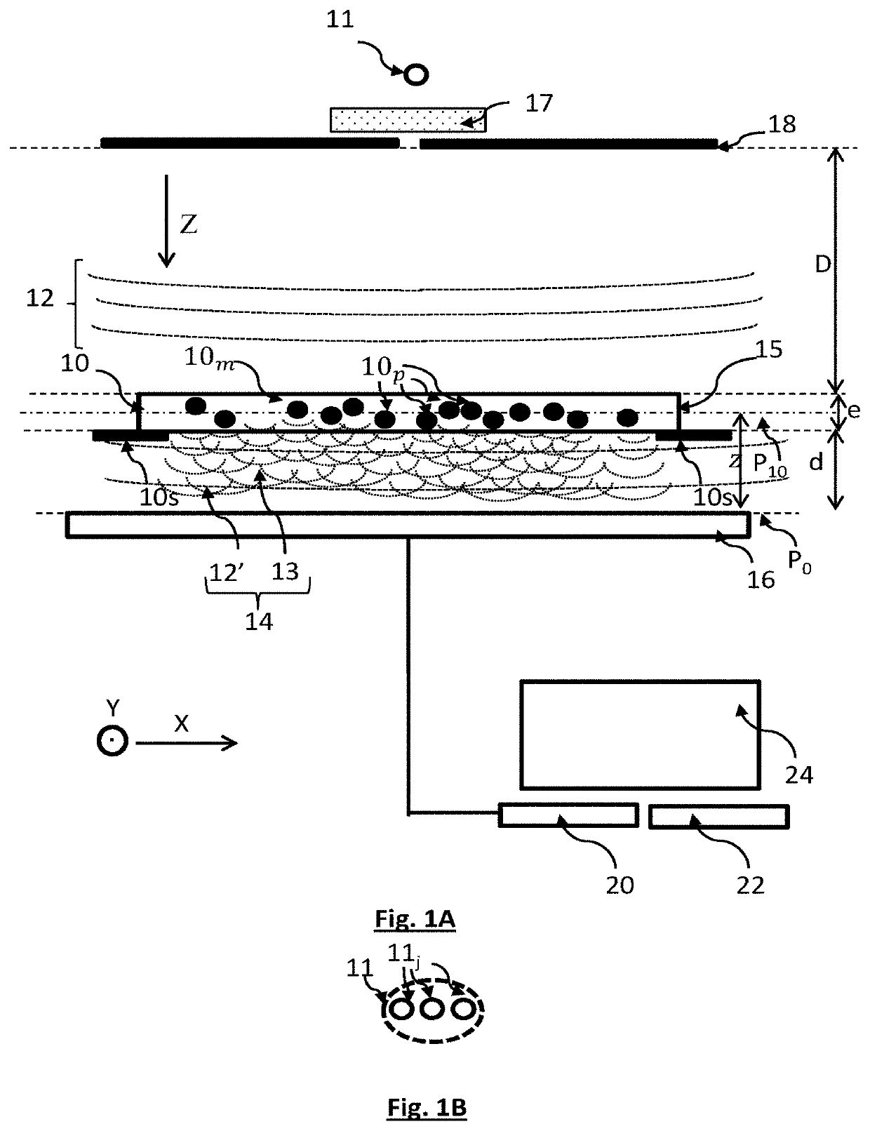
[0136]An example has been carried out using a sample containing cells of A549 type placed in a sample containing a liquid culture medium, at a distance of 1400 μm from a CMOS image sensor: size of the pixels: 1.67 μm×1.67 μm-10 million pixels. The light source comprised 3 light-emitting diodes that emitted in the red, green and blue, respectively. The light source was placed at a distance of 50 mm from the sample. It was coupled to a diaphragm defining a diameter aperture of 50 μm.

[0137]FIGS. 4A, 4B and 4C shows the images acquired in the red, green and blue spectral bands, respectively.

[0138]FIG. 4D shows an image of the gradient Gwn(r) of the validity indicator established for each pixel r, as a function of the parameter L(r) in the first iteration (n=1). In this example, the validity indicator is such that:

ϵ|ℱnn=ϵ0|ℱnn+γϵ10|ℱnn(24)withϵ0|ℱnn=4NrNλ∫dr∑λ(M^0λ,n-M0λ)2and(25)ϵ10|ℱnn=∫dr(∂Ln(r)∂x)2+(∂Ln(r)∂y)2+(Ln(r))2(26)

[0139]FIG. 4E shows a spatial distribution of the optical thic...


PUM

PropertyMeasurementUnit
diameteraaaaaaaaaa
diameteraaaaaaaaaa
diameteraaaaaaaaaa

Abstract

A method for observing a sample (10), the sample lying in a plane of the sample defining radial coordinates, the method comprising the following steps:
    • a) illuminating the sample using a light source (11), able to emit an incident light wave (12) that propagates toward the sample along a propagation axis (Z);
    • b) acquiring, using an image sensor (16), an image (I0) of the sample (10), said image being formed in a detection plane (P0), the sample being placed between the light source (11) and the image sensor (16), such that the incident light wave sees an optical path difference, parallel to the propagation axis (Z), by passing through the sample;
    • c) processing the image acquired by the image sensor;
wherein the processing of the acquired image comprises taking into account vectors of parameters, respectively defined at a plurality of radial coordinates, in the plane of the sample, each vector of parameters being associated with one radial coordinate, and comprising a term representative of an optical parameter of the sample, at least one optical parameter being an optical path difference induced by the sample at the radial coordinate, the vectors of parameters describing the sample.

Description

TECHNICAL FIELD[0001]The technical field of the invention is related to the observation of a sample, in particular a biological sample, by lensless imaging, employing a holographic reconstruction algorithm of improved performance.PRIOR ART[0002]The observation of samples, and in particular biological samples, by lensless imaging has seen substantial development over the last ten years. This technique allows a sample to be observed by placing it between a light source and an image sensor, without placing any optically magnifying lenses between the sample and the image sensor. Thus, the image sensor collects an image of the light wave transmitted by the sample.[0003]This image is formed of interference patterns generated by interference between the light wave emitted by the light source and transmitted by the sample, and diffracted waves resulting from the diffraction, by the sample, of the light wave emitted by the light source. These interference patterns are sometimes called diffra...

Claims


Application Information

Patent Timeline
Patent Type & Authority Applications(United States)
IPC IPC(8): G01N33/483G03H1/04G01N15/14
CPCG01N2201/12G01N15/1434G01N33/4833G03H2001/0033G03H1/0443G01N15/1475G01N2015/1454G03H1/0866G03H2001/0447G03H2001/0452G03H2001/0471G03H2001/0816G03H2222/18
Inventor HERVE, LIONELALLIER, CEDRIC
Owner COMMISSARIAT A LENERGIE ATOMIQUE ET AUX ENERGIES ALTERNATIVES
Why Eureka
Try Eureka