
Label cost saving function

Active Publication Date: 2020-05-07
SATO HLDG CORP
View PDF3 Cites 1 Cited by
  • Summary
  • Abstract
  • Description
  • Claims
  • Application Information

AI Technical Summary

Benefits of technology

The present invention relates to adapting the layout of a printed matter to the amount of content to be printed. The invention allows for determining areas of the print medium which remain blank and modifying the layout data to reduce those blank areas. This can improve cost efficiency and readability. Additionally, the invention enables the user to modify the layout data to enlarge certain fields and reduce blank spaces between print fields. The user interface is simple and intuitive, allowing for flexibility in setting parameters and cancelling / replacing parameters. The invention also provides a way to set a predetermined maximum size of blank areas, giving users more flexibility in how to handle the content design. Overall, the invention enhances the efficiency and impact of printed materials.

Problems solved by technology

On the other hand, in view of the above, a font having a small point size may be required, which decreases the readability of the text.
A general problem that occurs in connection with employing a predefined layout or printing data on a medium resides in the fact that the amount of text to be printed may be considerably different between particular print items of the same type.
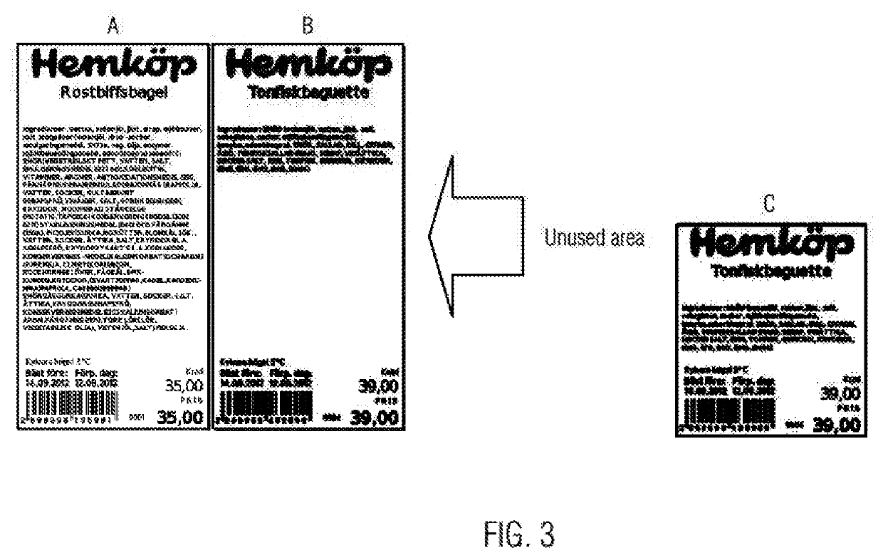
In situations where the text amount is much less than the maximum amount, this leads to many unused (blank or white) areas.
In particular, since the layout also defines the size of a label, a lot of paper will remain unused for printing and is thus wasted.
On the one hand, in view of the large number of labels printed every day, this leads to a considerable increase in costs, and on the other hand negatively affects ecology.
However, it is a drawback of such a method that it does not provide much flexibility.
Since the skipping is performed on the level of the print data, there is only the possibility of omitting a portion of the unused area, and no more adaptation to the layout, such as improved readability, can be made.
Moreover, a more complicated operation of the printer as compared to usual printers is necessary.

Method used


Image

  • Label cost saving function
  • Label cost saving function
  • Label cost saving function

Examples


Embodiment Construction

[0036]The present invention provides a system and computer-implemented method for flexibly adapting a layout of contents to be printed so as to optimize usage of available paper resources, minimize the usage of paper and increase the readability of the printed contents, by minimizing areas that remain unused for printing (blank). Moreover, embodiments of the present invention provide a computer-implemented graphical user interface which allows a user to set and modify parameters for defining and adapting the layout.

[0037]In the following, a detailed description will be given with reference to the figures of the drawings, in which like reference numerals represent like elements.

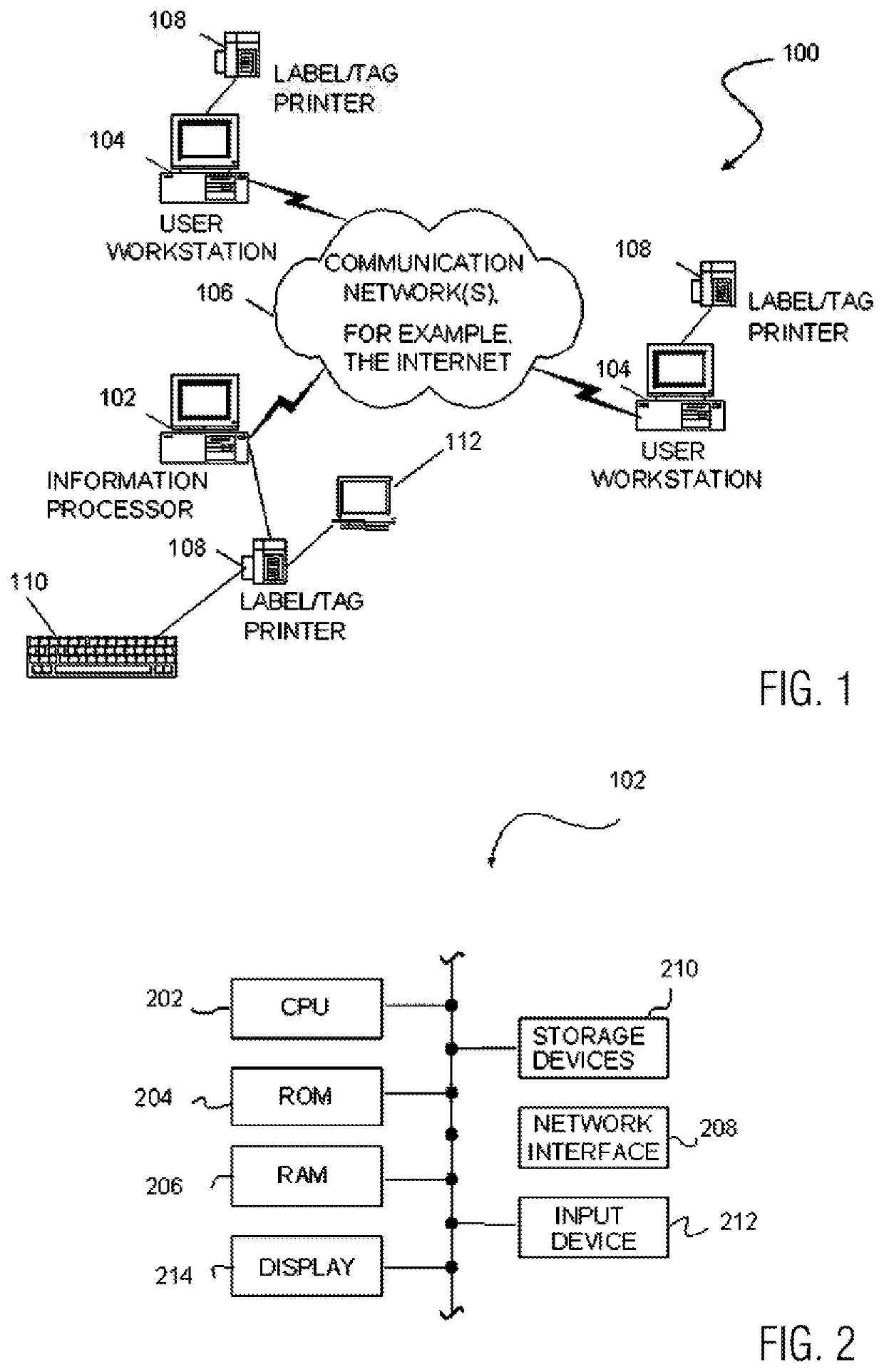
[0038]FIG. 1 illustrates an exemplary hardware arrangement of a printing environment, in the framework of which the present invention is employed, which is generally referred to as system 100.

[0039]System 100 preferably comprises at least one computing device (information processor 102 and / or user workstation ...


PUM


Abstract

The present invention provides a computer-implemented method and system for modifying given layout data on the basis of predetermined parameters for reducing unused white areas in accordance with a given printing layout. The invention is particularly applicable in the framework of label and tag printers employing continuous media. On the one hand, the reduction of unused white areas can lead to an overall reduction in the paper size, thus rendering the labels more environmentally friendly. On the other hand, the layout can also be improved, leading to a better usage of the available space for printing data thereon.

Description

FIELD OF THE INVENTION[0001]The present invention generally relates to printers, in particular to label and tag printers. More specifically, the present invention relates to a computer-implemented method for modifying print layouts, which can specifically be applied to reduce the costs of labels to be printed.BACKGROUND ART[0002]Printers, in particular label and tag printers, are devices capable of printing contents, in particular text and graphics, on a print medium such as a strip of paper. The print data are derived from contents data including, in particular, the text and / or graphics to be printed, and from layout data defining the layout of the content to be printed, such as print position, font type and point size, or the definition of particular fields in which text and / or graphics are to be printed. The definition of fields includes, in particular, the size (i.e. width and height) of the field, as well as the position thereof on the print medium and orientation information.[...

Claims


Application Information

Patent Timeline
IPC IPC(8): G06F3/12G06F40/103
CPCG06F3/1208G06F3/1243G06F3/1219G06F40/103G06F3/1242G06F3/125G06F3/1285G06F40/114H04N1/38
Inventor PETTERSSON, BENGTHEDBERG, MATSOTA, TAISAKU
Owner SATO HLDG CORP
Learn More