Holder for a curved duct portion

a duct portion and holder technology, applied in the direction of positive displacement liquid engines, machines/engines, prosthesis, etc., can solve the problems of reducing the diameter of at least a part of the duct portion and not accurately calculating the flow rate, so as to achieve effective long-term storage

Active Publication Date: 2020-05-14
ALLMED MEDICAL CARE HOLDINGS LIMITED
View PDF0 Cites 1 Cited by
  • Summary
  • Abstract
  • Description
  • Claims
  • Application Information

AI Technical Summary

Benefits of technology

[0013]The Applicant has thus faced the problem of avoiding deformation of the squeezable duct portion during long-time storage of tube pumps for the extracorporeal blood circuit.
[0014]The Applicant has found that an effective long time-storage without deforming the duct portion can be obtained by a holder comprising a supply-side ...

Problems solved by technology

This long-time storage affects the physical conformation of the squeezable duct deforming it.
According to this configuration, the duct portion tends to be defo...

Method used


Image

  • Holder for a curved duct portion
  • Holder for a curved duct portion
  • Holder for a curved duct portion

Examples


first embodiment

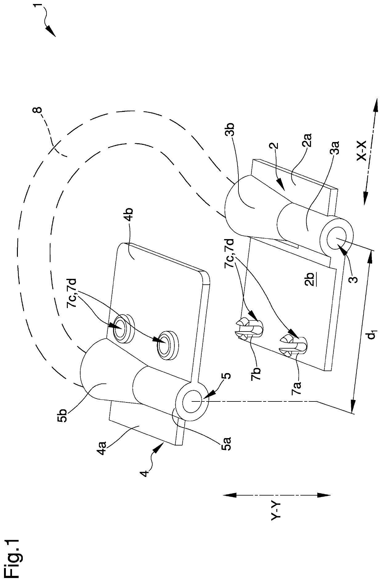
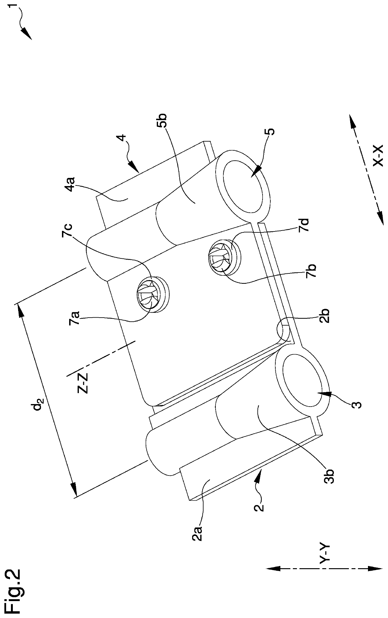
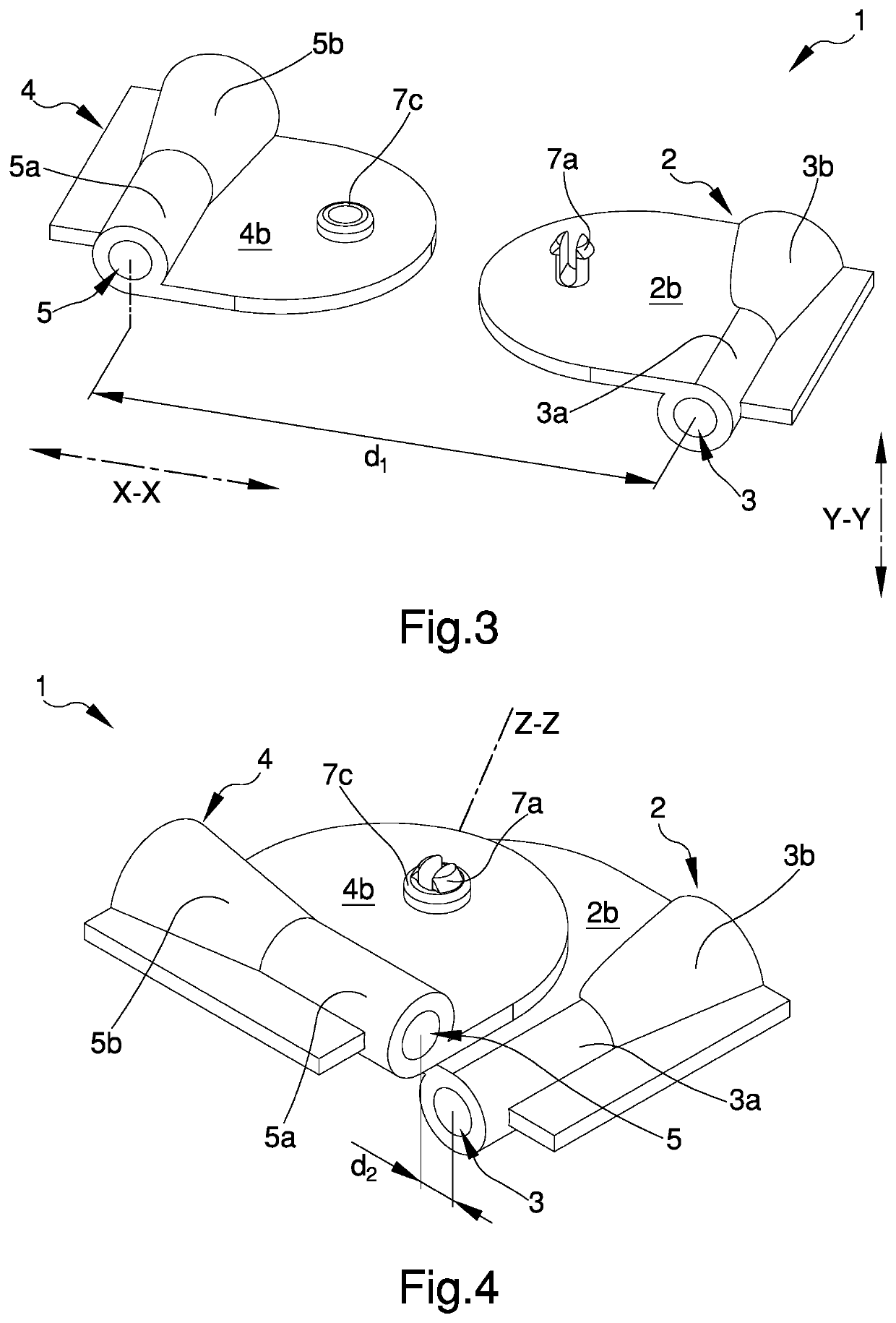
[0030] shown in the examples of FIGS. 1 and 2, the supply-side connector 2 has a preferably rectangular shape mainly extended for a predetermined length along a longitudinally direction X-X.

[0031]The cavity 3 is located substantially at the middle of the length of the supply-side connector 2. Similarly, the discharge-side connector 4 has a preferably rectangular shape where, substantially at the middle, is located the cavity 5. Preferably, the cavities 3,5 have circular section.

[0032]The supply-side connector 2 comprises a first plate 2a adapted to be connected to the pump 100 and a second plate 2b adapted to be removably connected to the discharge-side connector 4. Preferably, the first plate 2a is connected to the second plate 2b through the cavity 3. More preferably, first and second plate 2a, 2b are substantially coplanar extended. Similarly, the discharge-side connector 4 comprises a first plate 4a adapted to be connected to the pump 100 and a second plate 4b adapted to be remo...

second embodiment

[0049] shown in the examples of FIGS. 5 and 6, recesses 7c′,7d′ formed on the second plate 4b of the discharge-side connector 2 have elongated ring-shape for receiving pins 7a′,7b′ projecting from the second plate 2b of the supply-side connector 2. In this way, the pins 7a′,7b′ and the recesses 7c′,7d′ act as guiding means allowing the connectors 2,4 to linearly move one towards each other along the longitudinal direction X-X so that, in both the storage and the operating configuration, the cavities 3,5 are parallel aligned on a substantially same plane X-Z.

[0050]With reference to the example shown in FIG. 5, the holder 1 comprises connecting means for removably coupling the supply-side connector 2 to the discharge-side connector 4. In particular, the connecting means act on said connectors 2,4 to prevent them from movements when the latters are in the operating configuration. In particular, the supply-side connector 2 comprises a pin 17a which projects from the second plate 2b of t...

third embodiment

[0051] shown in the examples of FIGS. 7 and 8, the holder 1 comprises a pair of rotating means 11,12 acting on the connectors 2,4 for rotating them around parallelly rotating axes z1,z2. In this way, the connectors 2,4 are rotatably moved one towards the other so that, in the storage configuration (FIG. 7), the cavities 3,5 be substantially parallelly aligned on a first plane X1-Z1 and, in the operating configuration (FIG. 8), the cavities 3,5 are substantially aligned on a second plane X2-Z2 parallel to the first plane X 1-Z1. In particular, in the storage configuration, the cavities are rotated with respect to the operating configuration.

[0052]Preferably, the connectors 2,4 can rotate individually around the rotation axes z1,z2 between the storage configuration, wherein the first cavity 3 is positioned away from the second cavity 5, and the operating configuration, in which the first cavity 3 is close to the second cavity 5.

[0053]According to the embodiment shown in the example of...


PUM


Abstract

The holder for a curved duct portion of a tube pump comprises: a supply-side connector comprising a first cavity and a first plate connected together, the first cavity being adapted for receiving an end of the curved duct portion, and a discharge-side connector comprising a second cavity and a second plate connected together, the second cavity being adapted for receiving another end of the curved duct portion, where said connectors are movable the one with respect to the other between a storage configuration, in which the supply-side connector is positioned away to the discharge-side connector, and an operating configuration, in which the supply-side connector is close to the discharge-side connector and in which the first and second plate are engaged together substantially on a same plane.

Description

TECHNICAL FIELD[0001]The present invention refers to a holder for a curved duct portion of a tube pump for extracorporeal blood circuits.BACKGROUND ART[0002]Typically, tube pumps are used as blood pumps or fluid replacement pumps in apparatuses for dialysis treatment and they are configured to pump a fluid by squeezing a curved tube by means of a rotor.[0003]Before starting the dialysis treatment, technical operators, like nurses or doctors, have to perform some preliminary activities for preparing the device as, for example, connecting tubes to / from the tube pump through relative connectors. In order to simplify these activities, a plurality of solutions has been proposed.[0004]EP2397695 discloses a tube pump comprising a rotor to squeeze a curved portion of a duct. The duct is provided with a supply tube connected to an end of the curved portion via a supply-side connector and a discharge tube connected to the other end of the curved portion via a discharge-side connector. A singl...

Claims


Application Information

Patent Timeline
IPC IPC(8): A61M1/10F04B43/12A61M1/36F04B43/00
CPCA61M1/1006A61M1/3621A61M2205/3334F04B43/1253A61M1/1086F04B43/0072F04B43/12A61M60/113A61M60/279A61M60/109A61M60/462
Inventor DELNEVO, ANNALISA
Owner ALLMED MEDICAL CARE HOLDINGS LIMITED
Why Eureka
Try Eureka