Method of manufacturing head chip and method of manufacturing liquid jet head

a manufacturing method and liquid jet head technology, applied in the direction of manufacturing tools, printing, inking apparatus, etc., can solve the problems of reducing the yield ratio, and achieve the effect of increasing the yield ratio and suppressing the occurrence of failures

Active Publication Date: 2020-05-14
SII PRINTEK
View PDF0 Cites 0 Cited by
  • Summary
  • Abstract
  • Description
  • Claims
  • Application Information

AI Technical Summary

Benefits of technology

[0010]According to the first and the second method of manufacturing head chips and the method of manufacturing a liquid jet head related to an embodiment of the present disclosure, it becomes possible to suppress the occurrence of the failure in the process of forming the actuator plate to thereby increase the yield ratio.

Problems solved by technology

In a method of manufacturing such a head chip, there is a possibility that the yield ratio decreases due to, for example, a failure in a process of forming the actuator plate.

Method used


Image

  • Method of manufacturing head chip and method of manufacturing liquid jet head
  • Method of manufacturing head chip and method of manufacturing liquid jet head
  • Method of manufacturing head chip and method of manufacturing liquid jet head

Examples


Embodiment Construction

[0028]An embodiment of the present disclosure will hereinafter be described in detail with reference to the drawings. It should be noted that the description will be presented in the following order:

[0029]1. Embodiment (a method of manufacturing a liquid jet head using laser processing and surface removal processing)

[0030]2. Modified Example (an example of a method of manufacturing a liquid jet head using laser processing)

[0031]3. Other Modified Examples

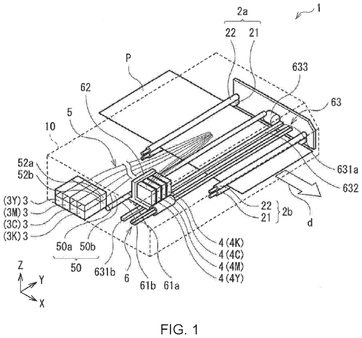
1. Liquid Jet Recording Device (Head Chip and Liquid Jet Head)

[0032]A liquid jet recording device according to an embodiment of the present disclosure will be described.

[0033]It should be noted that each of the head chip and the liquid jet head according to the embodiment of the present disclosure is a part of the liquid jet recording device described here. Therefore, each of the head chip and the liquid jet head will hereinafter be described in parallel.

[0034]The liquid jet recording device described here is, for example, a printer ...


PUM

PropertyMeasurementUnit
heightaaaaaaaaaa
pressureaaaaaaaaaa
conductiveaaaaaaaaaa

Abstract

There are provided a method of manufacturing a head chip capable of suppressing the occurrence of the failure in the process of forming the actuator plate to thereby increase the yield ratio, and a method of manufacturing a liquid jet head using the above method of manufacturing a head chip. The method of manufacturing a head chip according to an embodiment of the present disclosure is a method of manufacturing a head chip having an actuator plate adapted to apply pressure to liquid so as to jet the liquid. Forming the actuator plate includes forming a plurality of grooves on a surface of a piezoelectric substrate having one end and the other end so as to extend from the one end side toward the other end side, forming a conductive film on the surface of the piezoelectric substrate provided with the plurality of grooves, forming a laser processing area in the conductive film between the grooves adjacent to each other by performing laser processing from a start point on the one end side of the piezoelectric substrate to an end point on the other end side, and forming a surface removal area in at least a part including the start point and the end point out of the surface of the piezoelectric substrate by performing surface removal processing in a direction crossing the direction in which the laser processing is performed.

Description

RELATED APPLICATIONS[0001]This application claims priority to Japanese Patent Application Nos. 2018-211729 filed on Nov. 9, 2018, the entire content of which is incorporated herein by reference.BACKGROUND OF THE INVENTION1. Field of the Invention[0002]The present disclosure relates to a method of manufacturing a head chip and a method of manufacturing a liquid jet head.2. Description of the Related Art[0003]As a recording device for recording an image on a recording target medium, there has been known a liquid jet recording device equipped with a liquid jet head, and the liquid jet head includes a head chip for jetting a liquid. In the liquid jet recording device, the liquid is jetted from the head chip to the recording target medium, and thus, the image is recorded on the recording target medium.[0004]The head chip includes an actuator plate to electrically be driven for jetting the liquid. The actuator plate is provided with, for example, a plurality of grooves, and sidewalls in t...

Claims


Application Information

Patent Timeline
Patent Type & Authority Applications(United States)
IPC IPC(8): B41J2/16B23K26/362
CPCB41J2/1607B41J2/1623B23K26/362B41J2/1634B41J2/1621B41J2/14209B41J2/1609B41J2/1632B41J2/1642B41J2/18B41J2002/14491B41J2202/12B41J29/13
Inventor MUNAKATA, SUGURUNAKAMURA, YUJIKUBOTA, YUZURUIROKAWA, DAIKI
Owner SII PRINTEK
Why Eureka
Try Eureka