Vehicle system and a method of increasing efficiency of an engine

a technology of engine efficiency and vehicle system, which is applied in the direction of machines/engines, electric control, mechanical equipment, etc., can solve the problem of not wanting the recirculation of the portion of exhaust gas back to the engine cylinder, and achieve the effect of increasing the amoun

Inactive Publication Date: 2020-05-14
GM GLOBAL TECH OPERATIONS LLC
View PDF19 Cites 0 Cited by
  • Summary
  • Abstract
  • Description
  • Claims
  • Application Information

AI Technical Summary

Benefits of technology

[0033]E) adding extra fuel to the second subset of the plurality of cylinders via the respective fuel injector to

Problems solved by technology

During start-up or initial warm-up of the ICE, recirculation of the portion of the exhaust gas back to the engine cy

Method used


Image

  • Vehicle system and a method of increasing efficiency of an engine

Examples


Embodiment Construction

[0038]Those having ordinary skill in the art will recognize that all directional references (e.g., above, below, upward, up, downward, down, top, bottom, left, right, vertical, horizontal, etc.) are used descriptively for the FIGS. to aid the reader's understanding, and do not represent limitations (for example, to the position, orientation, or use, etc.) on the scope of the disclosure, as defined by the appended claims.

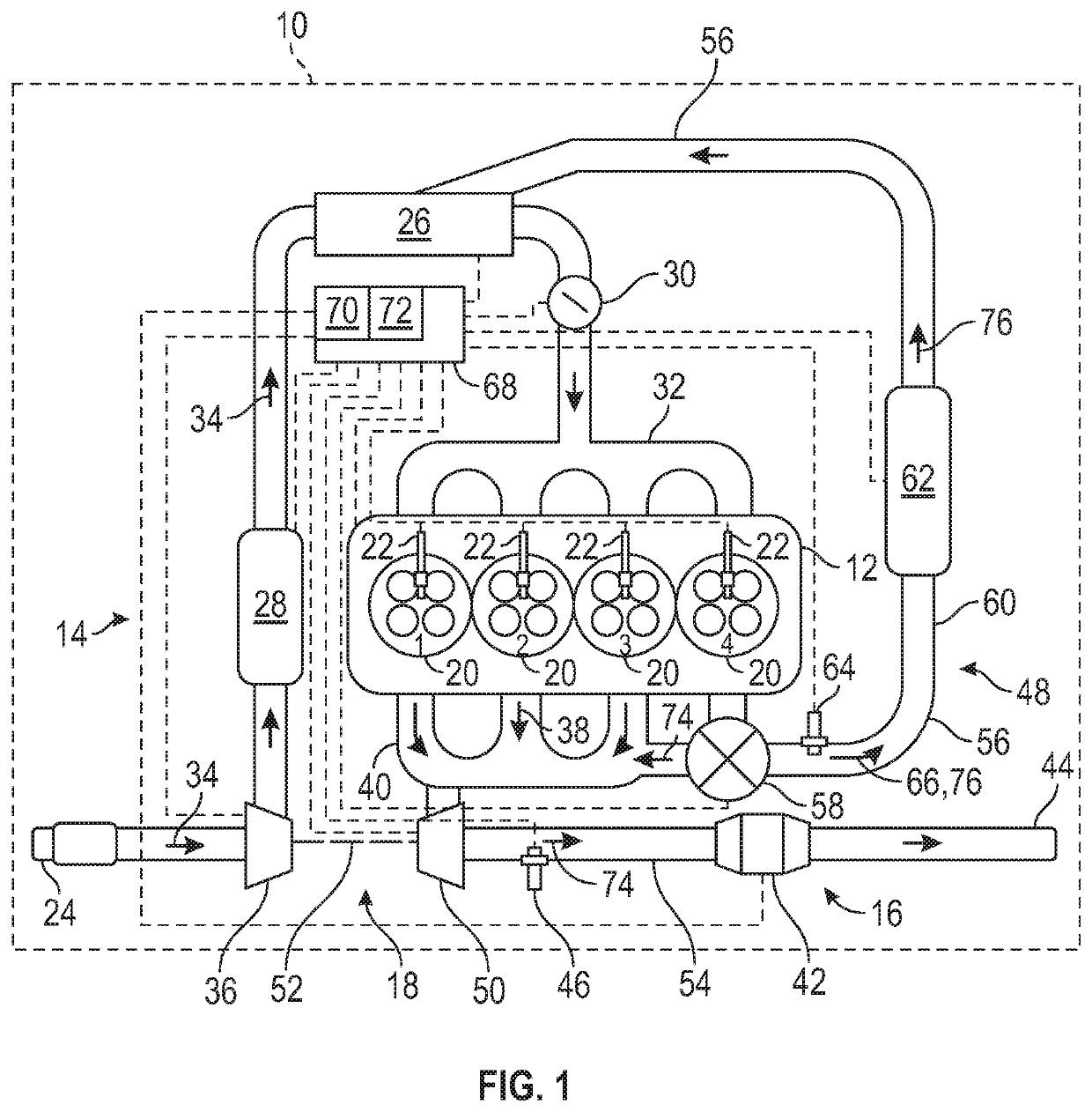
[0039]Referring to the FIGURE, wherein like numerals indicate like or corresponding parts throughout the several views, FIG. 1 schematically illustrates a vehicle system 10 of a motor vehicle including an engine 12, an air intake system 14, and an exhaust system 16. The air intake system 14 and the exhaust system 16 may each respectively be in fluid communication with the engine 12, and may be in mechanical communication with each other through a turbocharger 18.

[0040]The engine 12 may be an internal combustion engine, such as a spark-ignited internal combustion engi...


PUM


Abstract

A vehicle system includes an engine defining a plurality of cylinders and configured to combust a fuel. A method of increasing efficiency of an engine includes controlling an amount of fuel being injected into the plurality of cylinders of the engine via a respective fuel injector. An exhaust gas recirculation (EGR) system is in selective fluid communication with a second subset of the plurality of cylinders and the air intake system to route the second exhaust product from the second subset of the plurality of cylinders to an air intake system. A valve is coupled to the EGR system and the exhaust system. A first sensor is disposed between the valve and the air intake system, and measures an amount of reformate in the second exhaust product when the valve is in a second position.

Description

INTRODUCTION[0001]Internal combustion engines (ICE) combust a mixture of air and fuel within one or more combustion chambers to produce a mechanical output. During the combustion, various exhaust gases are produced. In some instances, a portion of the exhaust gas may be recirculated back into the engine cylinders (via an exhaust gas recirculation (EGR) system). In a gasoline engine, this inert exhaust may displace an amount of fresh air of a combustible mixture in the cylinder resulting in increased engine efficiency. The recirculated exhaust gas or EGR may reduce the combustion temperature in the cylinder which reduces heat transfer losses and / or may reduce the creation of certain gaseous byproducts. Displacement of fresh air may reduce pumping losses.[0002]During start-up or initial warm-up of the ICE, recirculation of the portion of the exhaust gas back to the engine cylinders may not be desired, and therefore, a valve may divert this exhaust gas out through an aftertreatment dev...

Claims


Application Information

Patent Timeline
IPC IPC(8): F02D41/14F02M26/16F02M26/46F02D41/38F02M26/22F02B29/04F02M26/19F02M26/05
CPCF02M26/22F02D2041/389F02D41/1439F02D2041/147F02M26/05F02D41/38F02D41/1444F02M26/16F02M26/46F02B29/04F02M26/19F02D41/0077F02D41/0082F02D41/30F02M26/43F02D41/0065F02D41/008Y02T10/12Y02T10/40
Inventor CASETTI, MARTINO A.LUCIDO, MICHAEL J.GE, PINGWHEELER, JENNIFER C.
Owner GM GLOBAL TECH OPERATIONS LLC
Why Eureka
Try Eureka