Friction engagement device

a friction engagement and friction component technology, applied in mechanical actuators, mechanical apparatus, failure to meet the requirements of safety, etc., can solve the problems of increased oil strainer impedance, abnormal wear of friction engagement devices constructed by friction components, and difficult oil strainer sucking

Active Publication Date: 2020-05-14
HONDA MOTOR CO LTD
View PDF0 Cites 4 Cited by
  • Summary
  • Abstract
  • Description
  • Claims
  • Application Information

AI Technical Summary

Benefits of technology

[0003]Therefore, in Patent Document 1, the friction engagement device includes a relief valve provided in an oil chamber in which the piston is located. In the process that the piston is moved relative to the friction components, a valve elastic component of the relief valve is also moved. When the piston moves more toward the friction components than in the normal case, the force applied by the valve elastic component lowers the oil pressure in the oil chamber, thereby detecting whether or not the friction components generates abnormal wear (that is, whether or not the oil pressure value is lower than the reference value). Furthermore, in Patent Document 2, the friction engagement device includes an elastic component and a load sensor disposed in a space in which the piston is located. In the process where the piston is moved relative to the friction components, the elastic component is also moved, and the load sensor is capable of detecting the compression load of the elastic component, thereby detecting whether or not the friction components generates abnormal wear (that is, whether or not the amount of change in the compression load exceeds the reference value), and notifying the driver of the warning information regarding the abnormal wear through a control component.

Problems solved by technology

However, when the surfaces of the friction components have scratches and burrs, the friction engagement device constructed by the friction components generates abnormal wear.
On this occasion, the size of the wear powder generated by the friction components becomes large and the wear powder may be generated in a large amount in a short time, causing an oil strainer connected to the friction engagement device to be clogged, and thus the impedance of the oil strainer increases.
On this occasion, it is difficult for the oil strainer to suck in oil; as a result, the oil pressure from the oil pump drops to failure.
Accordingly, the amount of stroke of the piston increases, and the amount of change in operation parameters such as the current value / torque of the motor also increases, which causes that the responsiveness of the oil pressure to be deteriorated, and the component is likely to fall off.

Method used


Image

  • Friction engagement device
  • Friction engagement device
  • Friction engagement device

Examples


Embodiment Construction

[0012]Reference will now be made in detail to the present embodiments of the disclosure, examples of which are illustrated in the accompanying drawings. Wherever possible, the same reference numbers are used in the drawings and the description to refer to the same or like parts.

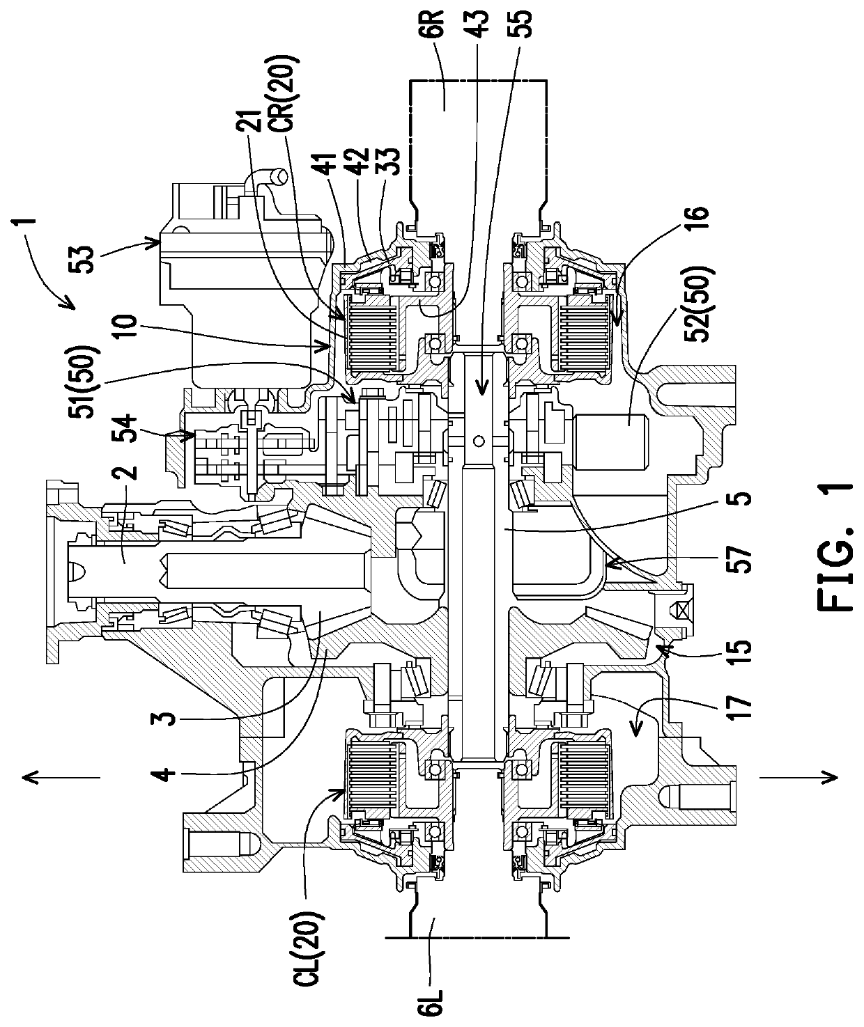
[0013]FIG. 1 is a cross-sectional view of a driving force transmission device 1 having a friction engagement device 20 according to an embodiment of the disclosure. Referring to FIG. 1, in the exemplary embodiment, it is exemplified that the friction engagement device 20 serves as a right clutch CR and a left clutch CL and is applied to the driving force transmission device 1. The driving force transmission device 1 includes a pinion shaft 2 connected to a propeller shaft (not shown) that is rotationally driven by a driving force transmitted from an engine (i.e., a driving source) not shown, a pinion gear 3 formed at the front end of the pinion shaft 2, and a ring gear 4 engaged with the pinion gear 3. Furthe...


PUM


Abstract

The friction engagement device connects the input shaft and the output shaft to transmit a driving force from a driving source from the input shaft to the output shaft. The friction engagement device includes a housing, a friction engagement portion, a piston, an oil pump, and a motor. The housing is disposed between the input shaft and the output shaft. The friction engagement portion is disposed in the housing and composed of a plurality of friction components. The piston is disposed at one side of the friction engagement portion for pressing the friction engagement portion. The oil pump is used to operate the piston. The motor is used to drive the oil pump. In the friction engagement device, abnormal wear of the friction components of the friction engagement portion is detected by monitoring a value of an operation parameter of the friction engagement device.

Description

BACKGROUNDTechnical Field[0001]The disclosure relates to a friction engagement device served as a clutch, a brake, and the like in a driving force transmission device.Description of Related Art[0002]In related art, a driving force transmission device mounted on vehicles includes a hydraulic type of friction engagement device (for example, a clutch or a brake). As this type of friction engagement device, it generally includes a housing, a plurality of friction components disposed in the housing, and a piston disposed on one side of the friction components, and the piston can press the friction components by being pushed through oil pressure of an oil pump driven by a motor. However, when the surfaces of the friction components have scratches and burrs, the friction engagement device constructed by the friction components generates abnormal wear. On this occasion, the size of the wear powder generated by the friction components becomes large and the wear powder may be generated in a l...

Claims


Application Information

Patent Timeline
Patent Type & Authority Applications(United States)
IPC IPC(8): F16D48/06F16D25/0638F16D13/38
CPCF16D25/0638F16D48/066F16D13/38F16D2121/04F16D2500/5023F16D2500/1026B60T17/22B60T2270/40F16D66/02F16D2066/005F16D2066/008F16D48/06F16D2500/10412F16D2500/3022F16D2500/3024F16D2500/3058F16D2500/3065
Inventor NIWATA, KENJIIKARI, MOTONOBUFUJINUMA, SACHI
Owner HONDA MOTOR CO LTD
Why Eureka
Try Eureka