Compact high density rotary optical filter wheel assemblies

a technology of rotary optical filter wheel and high density, which is applied in the direction of optical radiation measurement, instruments, spectrometry/spectrophotometry/monochromators, etc., can solve the problems of limited compact solutions, high manufacturing cost, and limited method in the maximum number of channels achieved, so as to achieve high channel density and additional channel flexibility

Active Publication Date: 2020-05-14
LI COR
View PDF0 Cites 1 Cited by
  • Summary
  • Abstract
  • Description
  • Claims
  • Application Information

AI Technical Summary

Benefits of technology

[0003]Various embodiments advantageously provide filter wheel assemblies with a single actuation point to control positioning of front and rear optical filter elements simultaneously. The various assembly embodiments also provide high channel density with a plurality of selectable optical filter pairs. In some embodiments, each optical filter pair includes a rejection filter element for rejecting excitation light and a complementary emission filter element. In some embodiments, a window, a non-filtering optical component, or other optical components may be used in place of any filter element (e.g. imaging non-fluorescent or non-excitable materials). In some embodiments, a two-level offset filter wheel configuration is implemented. In some embodiments, additional channel flexibility is implemented by use of long-pass excitation rejection filters rather than band-pass filters.

Problems solved by technology

Certain combinations of excitation / emission channels can be designed into a single set of fixed, multi-notch filters, however this method may be very limiting in the maximum number of channels achieved and may be expensive to manufacture.
Additionally, the need for each desired channel to have a specific combination of a front filter (i.e., at the imaging target side) that rejects the excitation wavelength and a rear filter (i.e., at imaging detector side) that passes only the emission wavelength leaves limited compact solutions and requires multiple actuators to independently control separate front and rear filters.

Method used


Image

  • Compact high density rotary optical filter wheel assemblies
  • Compact high density rotary optical filter wheel assemblies
  • Compact high density rotary optical filter wheel assemblies

Examples


Embodiment Construction

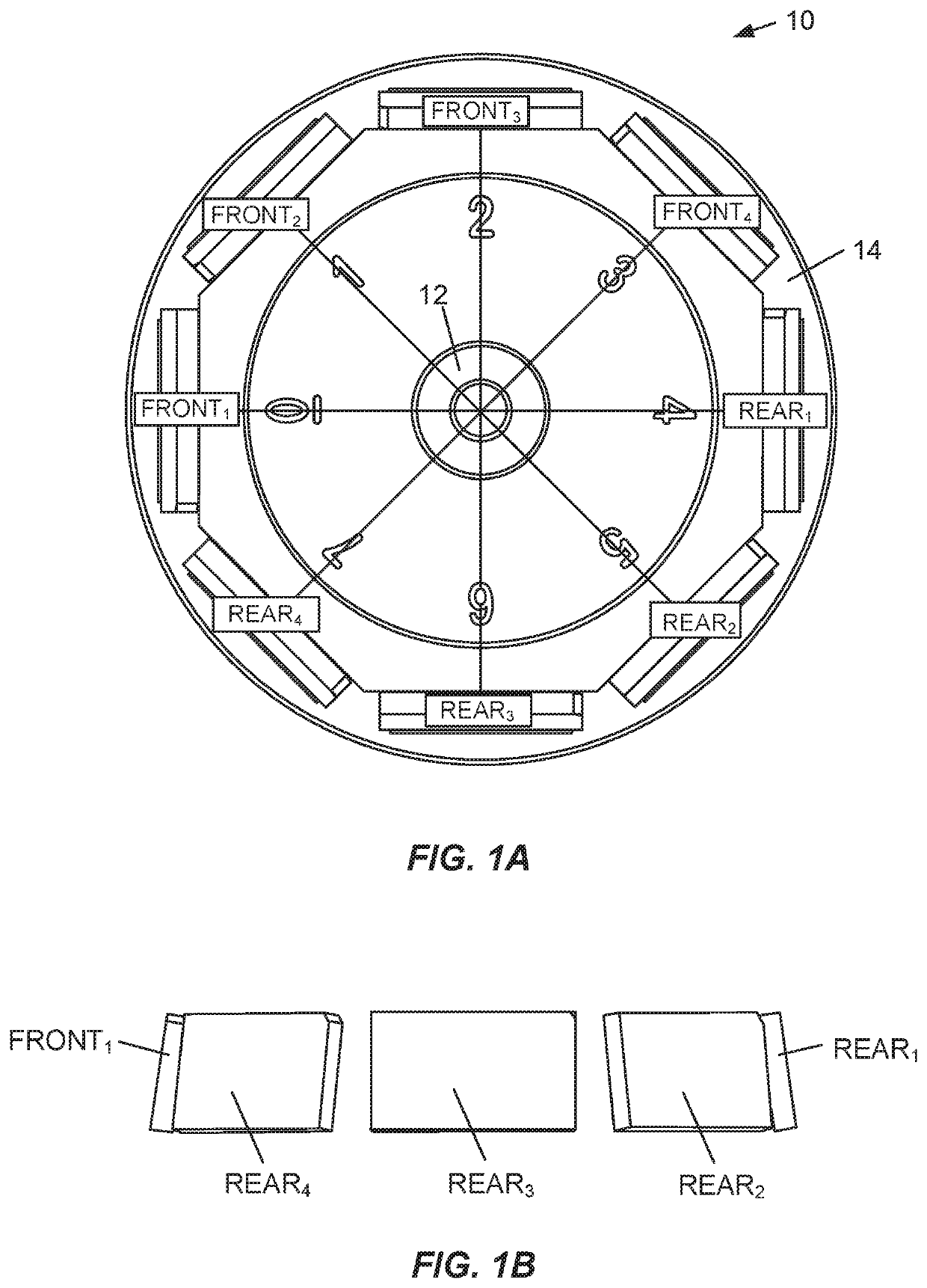
[0025]FIG. 1A illustrates a top view of a single-level filter wheel assembly 10 according to an embodiment. The filter wheel assembly 10 includes a body structure 14 configured to hold a plurality of optical filter pairs arranged around an axis 12, e.g., an axis common to the plurality of optical filter pairs. In the specific embodiment shown in FIG. 1A, four optical filter pairs corresponding to four different positions or channels are shown, where each optical filter pair includes a first filter element and a complementary filter element. It should be appreciated that other embodiments may contain two or more optical filter pairs or two or more optical component pairs or a mixture of optical filter element and optical component pairs. Optical components might include optically transparent windows, mirror elements, refractive or diffractive elements, or other elements that direct or condition an incident light. In FIG. 1A, each first filter element is designated as a “Front” filter...


PUM


Abstract

Filter wheel assemblies with a single actuation point to control positioning of front and rear optical filter elements simultaneously and to provide high channel density with a plurality of selectable optical filter pairs. A filter wheel assembly may include a plurality of optical filter element pairs arranged around a common axis, wherein each of the plurality of optical filter element pairs includes a first filter element and a complementary filter element, wherein each first filter element and each complementary filter element has a surface having a normal component directed toward an inner portion of the filter wheel assembly.

Description

CROSS REFERENCES TO RELATED APPLICATIONS[0001]This patent application claims priority to U.S. Provisional Patent Application No. 62 / 767,385, entitled “COMPACT HIGH DENSITY ROTARY OPTICAL FILTER WHEEL ASSEMBLIES,” filed Nov. 14, 2018, which is incorporated herein by reference in its entirety.BACKGROUND[0002]The desire to add more channel options to a single optical imaging system (i.e. fluorescence imaging system) to take advantage of the maximum number of excitation / emission combinations has generally increased the size of the imaging system. Certain combinations of excitation / emission channels can be designed into a single set of fixed, multi-notch filters, however this method may be very limiting in the maximum number of channels achieved and may be expensive to manufacture. Additionally, the need for each desired channel to have a specific combination of a front filter (i.e., at the imaging target side) that rejects the excitation wavelength and a rear filter (i.e., at imaging de...

Claims


Application Information

Patent Timeline
Patent Type & Authority Applications(United States)
IPC IPC(8): G01J1/04G02B5/20G01J1/42
CPCG01J1/42G01J1/0492G02B5/201G02B26/008G01J1/4204G01J1/0488G01J1/0418G01J1/0271G01J2003/1217G01J2003/1221G01J3/18G01J3/2823G01J2003/2826G01J3/0213G02B17/0615G02B13/22G01J3/0235
Inventor RAGATZ, ANDREW GEORGELESIAK, CHRISTOPHERNICHOLLS, IRMAFIELDER, MARKBOUZID, AHMED
Owner LI COR
Why Eureka
Try Eureka