System component in an imaging system

a technology of system components and imaging systems, applied in the field of system components in imaging systems, can solve the problems of primary side thermal load that cannot exceed a predefined temperature limit, and achieve the effect of improving the utilization rate of system components

Inactive Publication Date: 2020-05-14
SIEMENS HEALTHCARE GMBH
View PDF0 Cites 0 Cited by
  • Summary
  • Abstract
  • Description
  • Claims
  • Application Information

AI Technical Summary

Benefits of technology

[0014]With the determination of the power induced heating based on the average power the imaging sequence may be configured such that the system component is used in such a way that a heating of the primary side below its maximum value is obtained and the heating may be closer to the maximum value of the temperature limit than obtained with other methods, thus improving the utilization of the system component.

Problems solved by technology

The imaging system includes a primary side or supply side configured to provide power to the system component resulting in a thermal load on the primary side that must not exceed a predefined temperature limit.

Method used


Image

  • System component in an imaging system
  • System component in an imaging system
  • System component in an imaging system

Examples


Embodiment Construction

[0034]In the following, embodiments are described in detail with reference to the accompanying drawings. The drawings are to be regarded as being schematic representations, and elements illustrated in the drawings are not necessarily shown to scale. Rather, the various elements are represented such that their function and general purpose becomes apparent to a person skilled in the art. Any connection or coupling between functional blocks, devices, components of physical or functional units depicted in the drawings and described hereinafter may be implemented by an indirect connection or coupling. A coupling between components may be established over a wired or wireless connection. Functional blocks may be implemented in hardware, software, firmware, or a combination thereof.

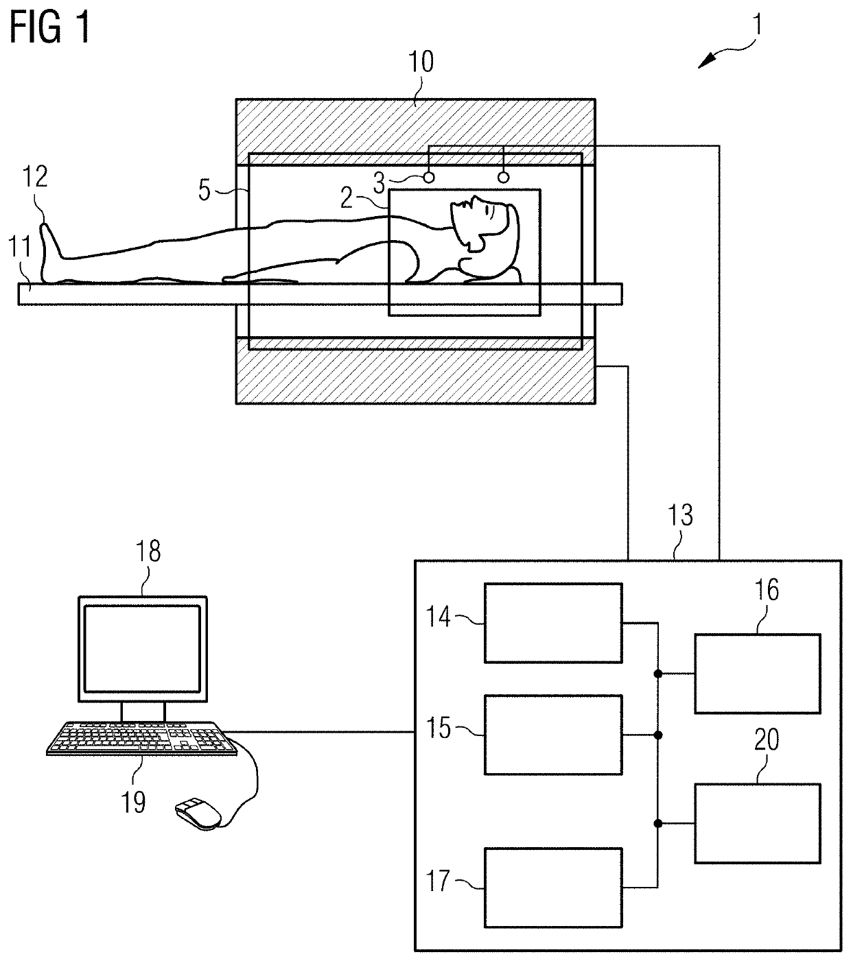
[0035]FIG. 1 depicts a schematic view of an MR system 1 that is configured to provide an operating mode in which the use of a system component such as the RF amplifier or the use of the magnetic field gradients i...


PUM


Abstract

Systems and methods are provided for determining a use of a system component in an imaging system. The imaging system includes a primary side configured to provide power to the system component and a secondary side including the system component that uses the power provided by the primary side during the image sequence. The method includes determining the use of the system component during an imaging sequence, determining a time averaged power provided by the primary side during the imaging sequence, determining a maximum time averaged power that may be provided by the primary side until a temperature limit is reached on the primary side. Further, whether the time averaged power is smaller than the maximum time averaged power is determined.

Description

CROSS REFERENCE TO RELATED APPLICATIONS[0001]This application claims the benefit of EP18206297.6, filed on Nov. 14, 2018, which is hereby incorporated by reference in its entirety.FIELD[0002]Embodiments relate to a method for determining a use of a system component in an imaging system in which at least one image of an object under examination is generated during the imaging sequence.BACKGROUND[0003]For the generation of images of an object under examination such as a patient, system components of the imaging systems are used. An example of such a system component may be the amplifier used to generate magnetic field gradients applied in an MR system, the RF amplifier used in an MR system, the power generating unit in an imaging system using x-rays etc. All the system components include some physical limits as the power required to drive the system components is limited and as the power may overheat the system component or any other component involved. There is a need to provide cost...

Claims


Application Information

Patent Timeline
Patent Type & Authority Applications(United States)
IPC IPC(8): G01R21/00G01R33/36
CPCG01R33/36G01R21/005G01R33/20G01R33/38A61B5/055G01R33/3852G01R33/543
Inventor FEIWEIER, THORSTENKÖHLER, MICHAELLENZ, HELMUTGRÜBEL, SÖREN
Owner SIEMENS HEALTHCARE GMBH
Why Eureka
Try Eureka