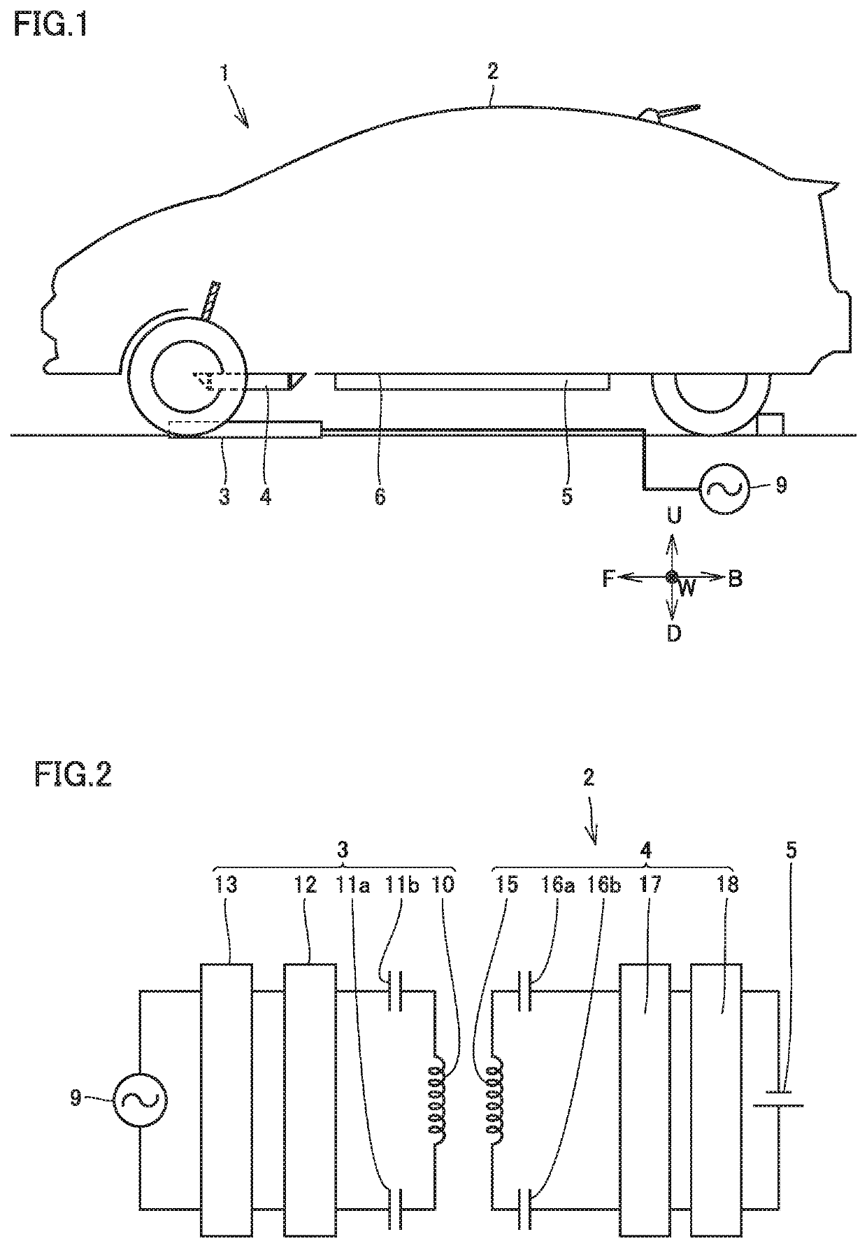
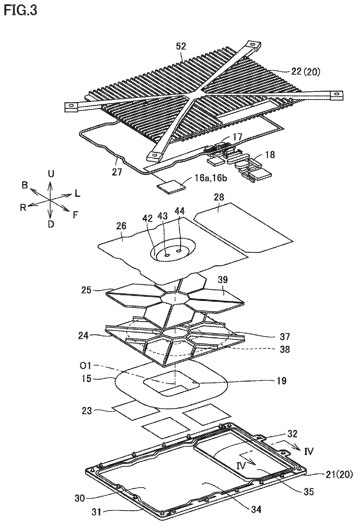
Coil unit
- Summary
- Abstract
- Description
- Claims
- Application Information
AI Technical Summary
Benefits of technology
Problems solved by technology
Method used
Image

Examples
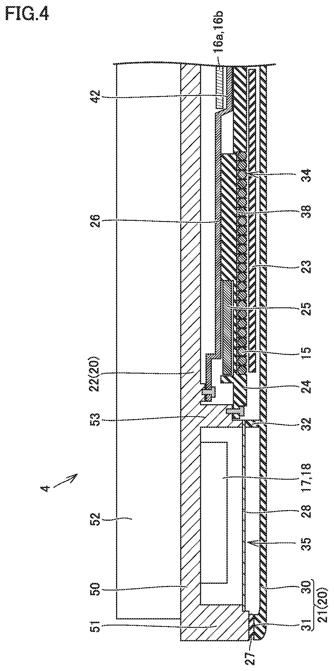
case 20
[0048]Case 20 includes a resin cover 21 and a body 22.
[0049]As shown in FIG. 4, body 22 includes a top plate 50, a peripheral wall 51, a cooling plate 52, and a partition wall 53. Top plate 50 is disposed on the upper side of body 22. Peripheral wall 51 extends downward from the outer peripheral edge of top plate 50. Peripheral wall 51 has a ring shape along the outer peripheral edge of top plate 50. A plurality of cooling plates 52 are formed on the upper face of top plate 50.
[0050]In FIG. 3, resin cover 21 is disposed on the lower side of case 20. Resin cover 21 includes a bottom plate 30, a peripheral wall 31, and a frame wall 32. Bottom plate 30, peripheral wall 31, and frame wall 32 are composed of, for example, resin. Peripheral wall 31 rises up from the outer peripheral edge of bottom plate 30.
[0051]Frame wall 32 partitions the space in case 20 into a coil space 34 and a device space 35, in cooperation with partition wall 53 shown in FIG. 4.
[0052]Protective sheet 23, power re...
PUM
 Abstract
Description
Claims
Application Information
 - R&D
- Intellectual Property
- Life Sciences
- Materials
- Tech Scout
- Unparalleled Data Quality
- Higher Quality Content
- 60% Fewer Hallucinations
Browse by: Latest US Patents, China's latest patents, Technical Efficacy Thesaurus, Application Domain, Technology Topic, Popular Technical Reports.
© 2025 PatSnap. All rights reserved.Legal|Privacy policy|Modern Slavery Act Transparency Statement|Sitemap|About US| Contact US: help@patsnap.com