

Light-emitting tube array-type light source device, light source module using the same, and fluid treatment device using the same light source device
- Summary
- Abstract
- Description
- Claims
- Application Information
AI Technical Summary
Benefits of technology
Problems solved by technology
Method used
Image

Examples
embodiment 1
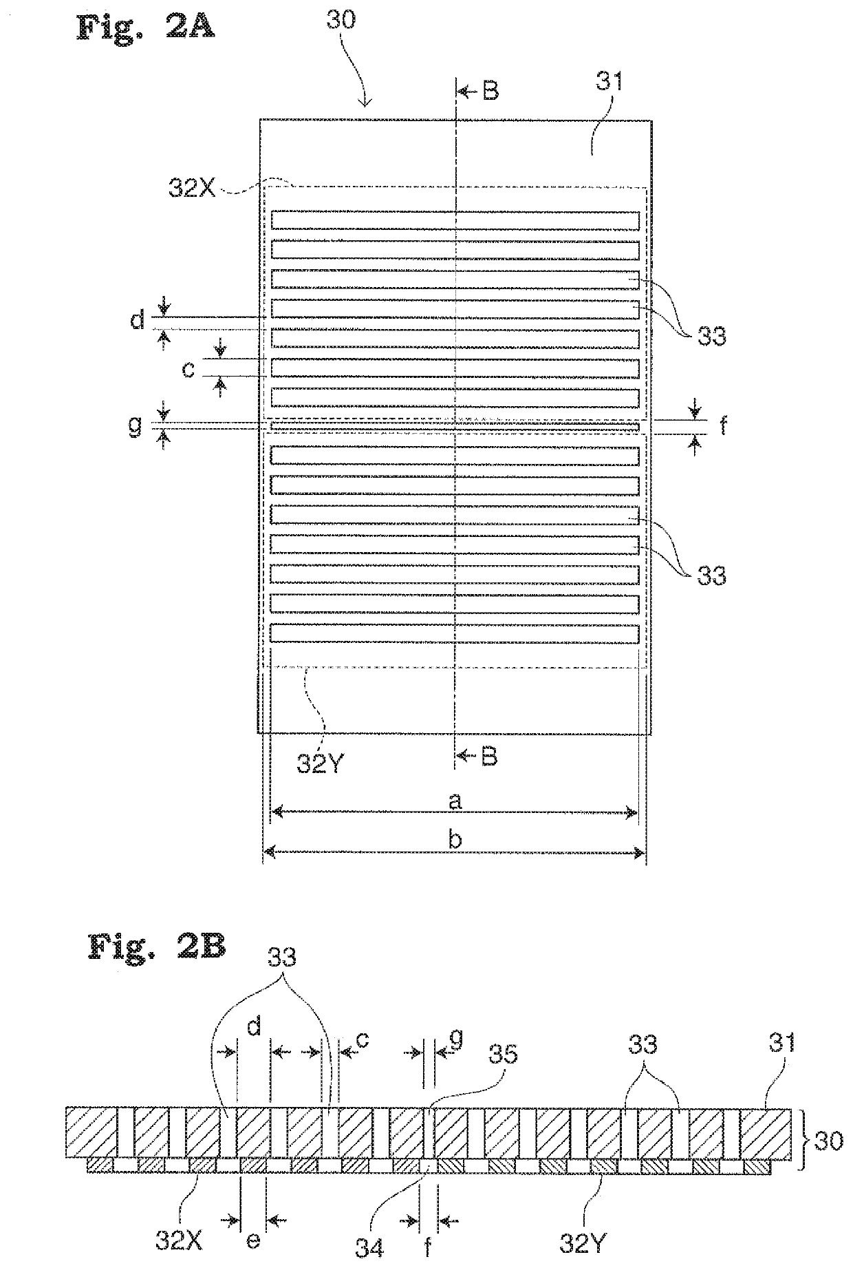
[0029]FIG. 2A illustrates a plan view indicating a structure of an electrode substrate in accordance with Embodiment 1 of the present invention; and FIG. 2B illustrates a cross-section view along arrows B-B in FIG. 2A. An electrode substrate 30 includes an insulating support body 31 and a pair of electrodes 32X, 32Y formed on a lower surface of the insulating support body 31. The electrode substrate 30 has, as a feature of the present invention, a plurality of slits (through-holes) 33 that penetrate through the insulating support body 31 and the electrodes 32X, 32Y and are aligned in parallel to each other.
[0030]The insulating support body 31 is made of a glass epoxy substrate having a thickness of 1 mm or less, preferably about 600 to 800 μm. The pair of electrodes 32X, 32Y is formed by patterning a metallic conductor layer on a lower surface of the glass epoxy substrate, the metallic conductor layer being formed by subjecting copper or aluminum to a plating process, an evaporation...
embodiment 2
[0047]FIG. 5 illustrates an explanatory transverse cross-section view of a light-emitting tube array-type light source device including an electrode substrate 60 in Embodiment 2 of the present invention. The pair of electrodes 32X, 32Y is placed on a lower surface of an insulating support body 61 that functions as a foundation of the electrode substrate 60; and the slits 33, 35 are formed in the electrode substrate 60 through the pair of electrodes 32X, 32Y and the insulating support body 61, in the same way as in the above-described Embodiment 1.
[0048]A feature of this Embodiment 2 is that a pair of auxiliary electrodes 62X, 62Y are placed at positions corresponding to both ends of the light-emitting tubes 11, respectively, and are placed on an upper surface of the electrode substrate 60. A pair of trigger electrodes 63X, 63Y are respectively placed at positions corresponding to proximity ends of the pair of electrodes 32X, 32Y forming the discharge gap therebetween.
[0049]The pair ...
embodiment 3
[0053]FIG. 6A illustrates a plan view indicating a structure of an electrode substrate of a flexible light-emitting tube array-type light source device in accordance with Embodiment 3 of the present invention; and FIG. 6B illustrates a diagrammatic cross-section view of the electrode substrate having light-emitting tubes placed thereon. Note that the number, widths, etc. of slit-like ventilation through-holes of the electrode substrate illustrated in the cross-section view of FIG. 6B do not precisely correspond to those illustrated in the plan view of FIG. 6A for the purpose of making the drawings simplified.
[0054]A light source device 70 in accordance with Embodiment 3 is characterized by its flexible structure. An electrode substrate 71 comprises a polyimide-based film substrate 72, which is a heat-resistant resin film known as, for example, Kapton (trade name), and an electrode conductor layer 73 formed of a copper foil or the like and laminated on the film substrate 72. The elec...
PUM
 Abstract
Description
Claims
Application Information