High flow nasal therapy system

a technology of high-flow nasal and therapy system, which is applied in the direction of inhalators, medical devices, other medical devices, etc., can solve the problems of inactivating/denaturing labile formulations, small aerosol delivery to the patient's respiratory tract, and high residual volume of jet and ultrasonic nebulizers, so as to avoid wastage of medication and remove any rainout in the breathing circui

Active Publication Date: 2020-05-21
STAMFORD DEVICES LTD
View PDF7 Cites 0 Cited by
  • Summary
  • Abstract
  • Description
  • Claims
  • Application Information

AI Technical Summary

Benefits of technology

The patent describes a device that delivers medication to patients through an aerosol. However, existing devices have problems with residual volumes and potential inactivation of labile formulations. The patent proposes a new device that can control the delivery of the aerosol to avoid these problems. The device delivers the inlet gas in a way that provides positive ventilator support during both inhalation and exhalation, and can also control the delivery based on detection of periods of non-activity or upon inspiratory pressure or flows to avoid wastage of the medication.

Problems solved by technology

A major problem with HFNT is that often only small quantities of aerosol are delivered to the patient's respiratory tract, due to losses during patient exhalation or droplet impaction in the high flows required for HFNT.
This is problematic during the delivery of HFNT therapy to paediatrics and neonates who can require flows in the range 1 to 3 l / min.
Also, both jet and ultrasonic nebulizers have high residual volumes.
Moreover, ultrasonic systems can overheat the medication thereby potentially inactivating / denaturing labile formulations.

Method used


Image

  • High flow nasal therapy system
  • High flow nasal therapy system
  • High flow nasal therapy system

Examples


Embodiment Construction

[0062]The invention will be more clearly understood from the following description of some embodiments thereof, given by way of example only with reference to the accompanying drawings in which:—

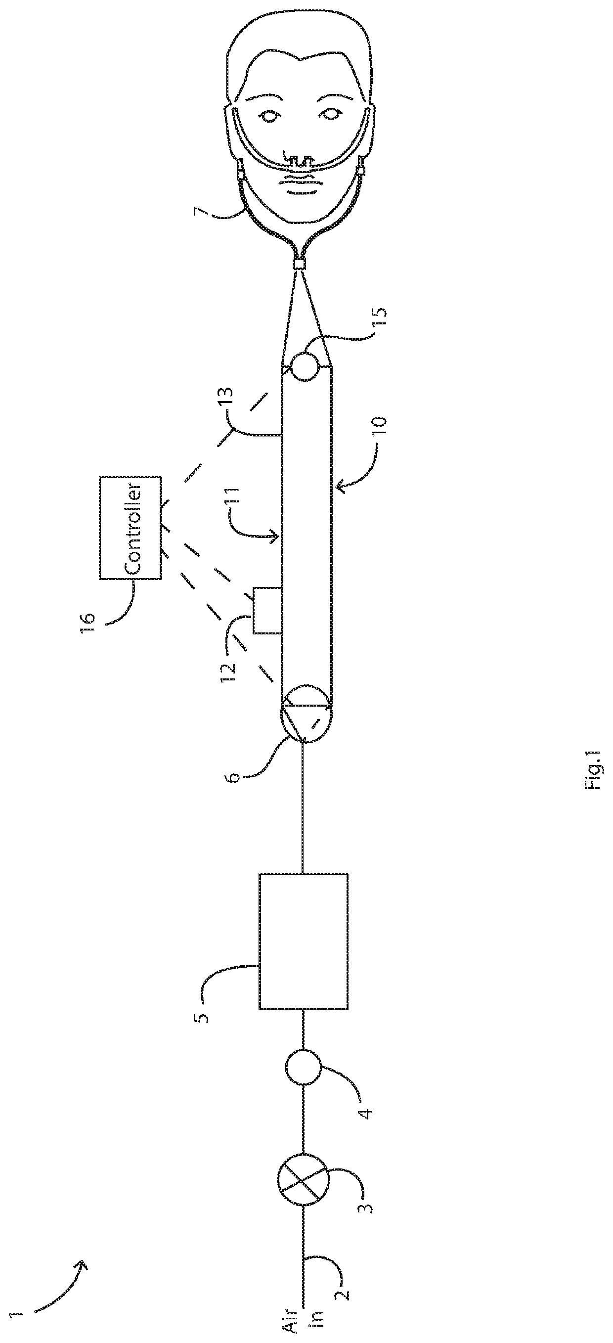
[0063]FIG. 1 is a diagram illustrating a HFNT system of the invention;

[0064]FIGS. 2(a) and 2(b) are diagrams showing different arrangements of limb size extending from the valve which controls flow into and between the limbs,

[0065]FIGS. 3(a) and 3(b) illustrate different control schemes with continuous variation between the limbs,

[0066]FIG. 4 is a set of plots showing emitted dose and respirable dose efficiencies recorded across actively controlled gas flow rates,

[0067]FIGS. 5(a) and 5(b) are diagrams showing different arrangements for connection of the limbs to a cannula, in which each limb feeds a single cannula prong only, and

[0068]FIG. 6 is a diagram illustrating an alternative system.

[0069]Referring to FIG. 1 a system 1 comprises a gas inlet 2 feeding a regulator 3, in turn feeding a ne...


PUM


Abstract

A high flow nasal therapy system (1) has a gas supply (2), a nebulizer (12), and a nasal interface (7). There are two branches (11, 10) and a valve (6) linked with the controller, the branches including a first branch (11) for delivery of aerosol and a second branch (10) for delivery of non-aerosolized gas. The controller controls delivery into the branches (11, 10), in which flow is unidirectional in the first and second branches, from the gas supply towards the nasal interface. The first branch (11) includes the nebulizer (12) and a line configured to store a bolus of aerosol during flow through the second branch (10). The valve (6) comprises a Y-junction between the gas inlet on one side and the branches on the other side.

Description

INTRODUCTION[0001]The invention relates to delivery of aerosol to the respiratory tract via the nasopharynx “high flow nasal therapy” (“HFNT”).[0002]Currently, aerosol can be delivered during HFNT using a vibrating mesh nebuliser (or other aerosol generator) and a T-piece positioned in the flow path.[0003]US2008 / 0017198 (Ivri) describes an aerosol delivery apparatus for pressure-assisted breathing systems.[0004]WO2013 / 163527 (Medstar Health) describes an aerosol system with an inspiratory limb and an expiratory limb.[0005]US2005 / 0284469 (Tobia et al) describes a system with a nebulizer and a gas monitoring device downstream of the nebulizer.[0006]WO2012 / 079684 / US2014 / 0290646 (NLI GmbH) describes a nasal inhalation device with a controller for applying a pattern to activation of an aerosol generator. This relies on exhalation down a separate dedicated limb whilst aerosol is being generated in the inspiratory limb.[0007]WO2005 / 048982 (Nektar) describes a ventilator circuit with aeroso...

Claims


Application Information

Patent Timeline
Patent Type & Authority Applications(United States)
IPC IPC(8): A61M16/16A61M16/08A61M16/10A61M16/20A61M16/06A61M11/00A61M16/14A61M15/08
CPCA61M16/0875A61M2016/0033A61M2205/3334A61M16/1095A61M2205/33A61M16/0666A61M16/16A61M11/00A61M2016/0036A61M16/0833A61M16/14A61M16/0866A61M2016/0018A61M16/202A61M2016/0027A61M15/08
Inventor MACLOUGHLIN, RONANSMITH, NIALL
Owner STAMFORD DEVICES LTD
Why Eureka
Try Eureka