Pressure Regulating Valve for Cupping Negative Pressure Apparatus

a negative pressure apparatus and pressure regulation valve technology, applied in mechanical equipment, separation processes, filtration separation, etc., can solve the problems of difficult easy to get lost during use or storage, and take a long time to obtain a replacement, so as to reduce the negative pressure force and reduce the noise generated by pressure relief

Inactive Publication Date: 2020-05-21
LIU PO CHANG +1
View PDF0 Cites 1 Cited by
  • Summary
  • Abstract
  • Description
  • Claims
  • Application Information

AI Technical Summary

Benefits of technology

[0007]A main object of the present invention is to provide an effective method for adjusting a negative pressure force to meet the demands of different users, and to ensure the effects achieved by negative pressure massage.
[0008]Another object of the present invention is to provide a quick-plug screw cap that is mounted on a cupping negative pressure apparatus, which effectively controls opening and closing of negative pressure communication holes of the cupping negative pressure apparatus, and is less likely to be lost.
[0009]A further object of the present invention is that the cupping negative pressure apparatus effectively filters impurities during suction and discharge action to ensure the maintenance of suction force and further reduce malfunction of the apparatus.
[0015]The pressure regulating valve for the cupping negative pressure apparatus of the present invention is further improved in that the metal screw structure inside the pressure regulating valve screw cap and the metal nut structure inside the pressure regulating valve body can be driven to be rotationally connected to a tightest state by rotating the pressure regulating valve screw cap. In the tightest state, the metal screw structure is capable of blocking the small holes on the metal nut structure inside the pressure regulating valve body, so that air is unable to flow to the pressure regulating valve body, and thus the negative pressure force is unaffected to maintain in its strongest state. When the metal screw structure and the metal nut structure are rotationally loosened, the metal screw structure moves upward to expose the small holes of the metal nut structure with gaps, so that air flows through the gaps to reach inside the pressure regulating valve body, thereby reducing the negative pressure force, and controlling an amount of air flowing to reach inside the pressure regulating valve body by rotating the pressure regulating valve screw cap in order to adjust a magnitude of the negative pressure force.
[0016]The pressure regulating valve for the cupping negative pressure apparatus of the present invention is further improved in that an outermost ring of the metal nut structure assembly seat is provided with a ring of muffler cover assembly seat to be capped by the muffler cover. The muffler cover is provided with a hole, the muffler cover passes through a top of the pressure regulating valve screw cap via the hole to be assembled with the muffler cover assembly seat of the metal nut structure assembly seat, so that retaining ring circulation holes of the pressure regulating valve body are located in an internal space formed by assembling the muffler cover and the muffler cover assembly seat. Thereby, pressure is relieved in the internal space and noise generated by pressure relief is buffered, and air is slowly circulated from a gap underneath the muffler cover and the pressure regulating valve screw cap to reach inside the pressure regulating valve body to reduce the noise generated by pressure relief.
[0018]The pressure regulating valve for the cupping negative pressure apparatus of the present invention is further improved in that outer sides of the negative pressure communication holes of the pressure regulating valve body are sleeved with the quick-plug screw caps, and the unused negative pressure communication holes are plugged by the quick-plug screw caps to prevent air from flowing through the unused negative pressure communication holes, which will affect the negative pressure.

Problems solved by technology

Although the conventional cupping negative pressure apparatus has been able to achieve certain massage effect, in actual application, because different users need to feel different negative pressure forces and effects being achieved, the conventional cupping negative pressure apparatus can not meet demands of different users.
When some of the negative pressure communication holes do not need to be operated, they are usually plugged with a soft plug, because the soft plug is not a structure of the conventional cupping negative pressure apparatus, it is easy to get lost during use or storage, and it takes time to obtain a substitute.
In addition, during the operation of negative pressure massage, since the user's body inevitably generates moisture or needs to be applied with essential oil, the conventional cupping negative pressure apparatus easily sucks in the substances and affects the suction force when performing suction and discharge action.
Therefore, it can be seen that the conventional technology still has drawbacks and needs to be researched and improved by the industry.

Method used


Image

  • Pressure Regulating Valve for Cupping Negative Pressure Apparatus
  • Pressure Regulating Valve for Cupping Negative Pressure Apparatus
  • Pressure Regulating Valve for Cupping Negative Pressure Apparatus

Examples


Embodiment Construction

[0025]A pressure regulating valve for a cupping negative pressure apparatus of the present invention will be further described below with reference to FIGS. 1 to 5 and specific embodiments. Other advantages and efficacies of the present invention will be readily apparent to those ordinarily skilled in the art from the contents disclosed by the description.

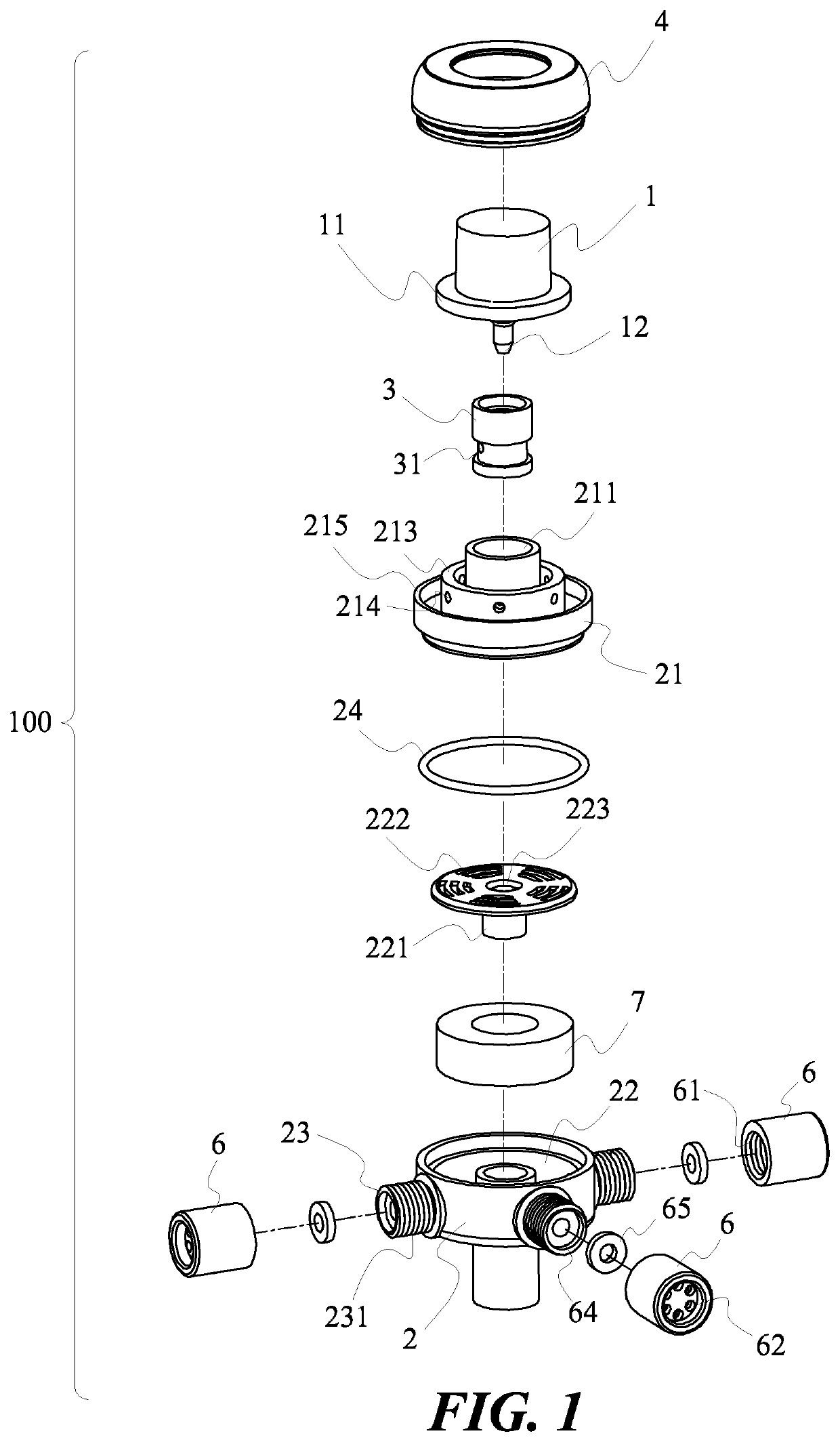
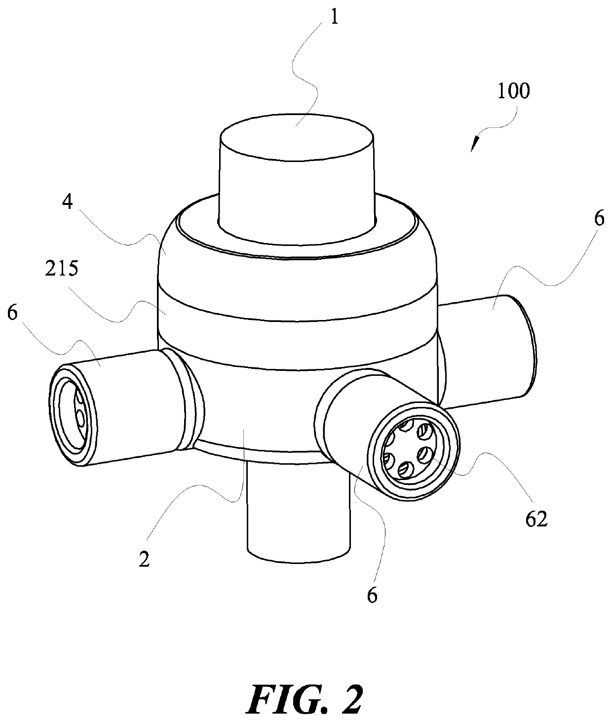
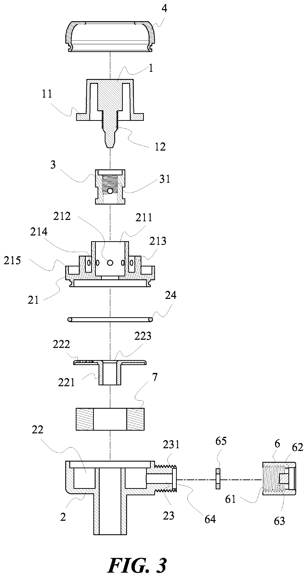
[0026]First, please refer to FIG. 1 to FIG. 4 of a pressure regulating valve 100 for a cupping negative pressure apparatus according to the present invention. The pressure regulating valve 100 can be divided into four components, including a pressure regulating valve screw cap 1, a pressure regulating valve body 2, a metal nut structure 3 and a muffler cover 4.

[0027]Further, inside the pressure regulating valve body 2 is provided with a pressure regulating valve filter trough 22, and a metal nut structure assembly seat 21 is disposed above the pressure regulating valve filter trough 22, the metal nut structure 3 is tightly mounted ...


PUM

PropertyMeasurementUnit
sizeaaaaaaaaaa
pressureaaaaaaaaaa
pressure forceaaaaaaaaaa

Abstract

A pressure regulating valve for a cupping negative pressure apparatus is provided with an upper pressure regulating valve screw cap and a lower pressure regulating valve body having a metal nut structure inside, and the metal nut structure is provided with a plurality of nut pressure relief holes. The pressure regulating valve screw cap can be tightened to block circulation of the nut pressure relief holes. A muffler cover assembly seat is disposed on an outermost side of a metal nut structure assembly seat for assembling a muffler cover, small holes for circulating air are disposed between the muffler cover and the metal nut structure assembly seat. The pressure regulating valve body has negative pressure communication holes for sucking and discharging air and the negative pressure communication holes are communicated or plugged by quick-plug screw caps. A filter cotton is disposed in the pressure regulating valve body.

Description

BACKGROUND OF THE INVENTIONField of Invention[0001]The present invention belongs to the field of health care devices, and more particularly relates to a pressure regulating valve for adjusting a negative pressure force of a cupping negative pressure apparatus.Related Art[0002]Cupping negative pressure apparatus is an easy-to-use health care device that has been widely promoted in the market. The cupping negative pressure apparatus is operated by connecting cupping cups with communicating tubes, an internal air pump of the apparatus is operated to achieve continuous suction vacuum effect, and a pressure relief valve releases a small amount of vacuum pressure when suction is stopped, so that the vacuum pressure inside the cupping cup produces actions of tightening and loosening, thus achieving massage effect on the human body.[0003]Although the conventional cupping negative pressure apparatus has been able to achieve certain massage effect, in actual application, because different use...

Claims


Application Information

Patent Timeline
Patent Type & Authority Applications(United States)
IPC IPC(8): F16K3/26G05D16/04F16K47/02B01D39/18A61M1/08A61M1/00
CPCB01D39/18G05D16/04F16K47/02F16K3/26A61M1/0035B01D46/24A61M2039/226A61M1/08A61M2205/42A61M2205/7536A61H9/0057F16K1/04F16K1/32A61H2009/0064A61H2201/0169A61H2201/1253A61H2201/1654A61H2201/5056A61M39/22A61M39/223A61M1/742A61M1/75F16K11/085A61M1/743
Inventor LIU, PO-CHANGLIU, SHIH-TA
Owner LIU PO CHANG
Why Eureka
Try Eureka