Radar sensor

a technology of radar sensor and sensor body, applied in the field of radar sensor, can solve the problems of limited solid angle of the monitored field of view, disadvantage of using a plurality of differently positioned radar sensors, and impaired spatial resolution and angular resolution of radar measurement, so as to improve the stability and susceptibility of radar sensor vibration, improve the accuracy of measurement, and reduce the weight

Active Publication Date: 2020-05-21
INDURAD
View PDF0 Cites 1 Cited by
  • Summary
  • Abstract
  • Description
  • Claims
  • Application Information

AI Technical Summary

Benefits of technology

[0017]In a further advantageous embodiment, the housing has a first end face and a second end face, with the pivot axis extending orthogonally through the first end face and orthogonally through the second end face and with the housing being rotatably supported at the frame at the first end face and at the second end face, in each case about the pivot axis. The durability, stability and susceptibility to vibration of the radar sensor are optimized by such a support of the housing at both sides.
[0018]The radar sensor in accordance with the invention preferably comprises a deflection apparatus for radio frequency signals arranged within the housing, with the deflection apparatus being rotatable about the axis of rotation and with the deflection apparatus for the deflection of the radio frequency signals irradiated from the transmission and reception unit being configured such that the radio frequency signals can be irradiated substantially orthogonally to the axis of rotation and the radiation direction of the radio frequency signals is rotatable about the axis of rotation and such that radio frequency signals reflected outside the radar sensor can be deflected onto the transmission and reception unit by means of the deflection apparatus. A very compact design of the radar sensor results from this that is less susceptible to interference since the transmission and reception unit is arranged as immovable within the housing and the rotation of the radiation direction of the primary signals about the axis of rotation is implemented solely by the rotation of the deflection apparatus.
[0019]The deflection apparatus preferably comprises a mirror, with the mirror having a plastic body that is manufactured by means of additive production and that has a reflective metal coating. In comparison with a mirror manufactured completely from metal, a mirror having a plastic body has a lower weight, whereby higher rotational frequencies of the deflection apparatus can be implemented, typically approximately 100 Hz instead of 50 Hz with purely metal mirrors. A faster scanning of the field of view of the radar sensor is thereby made possible, whereby the increase in size of the field of view in accordance with the invention is not necessarily accompanied by a corresponding increase in the measurement time.
[0020]In a further advantageous embodiment, the deflection apparatus comprises a drive for rotating the mirror, with the drive being arranged between the mirror and the transmission and reception unit about the axis of rotation and with a waveguide for radio frequency signals extending through the drive. On an arrangement of the drive of the deflection apparatus about the axis of rotation, a transmission can be dispensed with and a robust construction of the deflection apparatus results that is less susceptible to vibrations. A free passage of the primary and secondary radio frequency signals between the transmission and reception unit and the mirror of the deflection apparatus is ensured here by the waveguide extending in the interior of the drive.

Problems solved by technology

In practice, the finite beam divergence of the primary signal results in a beam expansion as the distance from the transmitter increases, whereby the spatial resolution and angular resolution of the radar measurement are impaired.
The limited solid angle of the monitored field of view that makes the use of a plurality of differently positioned radar sensors necessary is a disadvantage with such radar sensors of the prior art.

Method used


Image

  • Radar sensor
  • Radar sensor
  • Radar sensor

Examples


Embodiment Construction

[0021]Further measures improving the invention will be shown in more detail below together with the description of a preferred embodiment of the invention with reference to the Figures. There are shown:

[0022]FIG. 1 a schematic representation of an embodiment of the radar sensor in accordance with the invention;

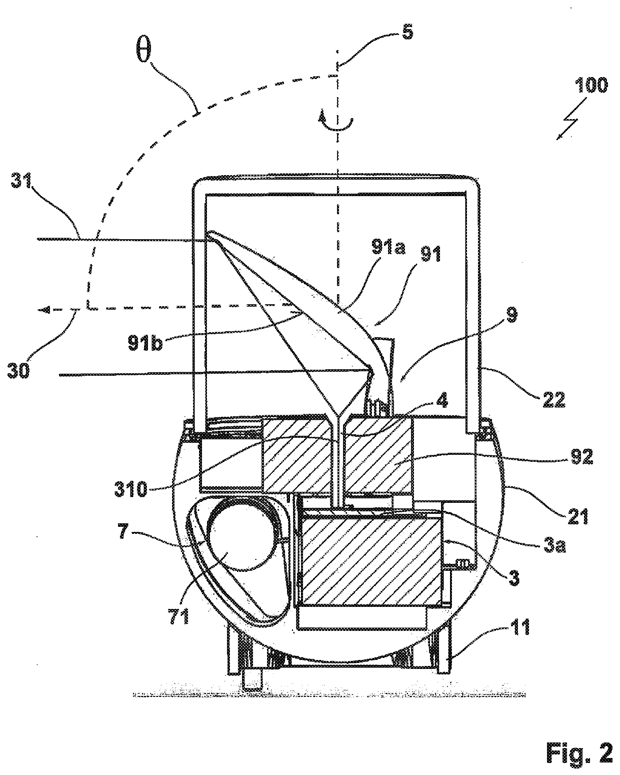
[0023]FIG. 2 a first sectional representation of the embodiment;

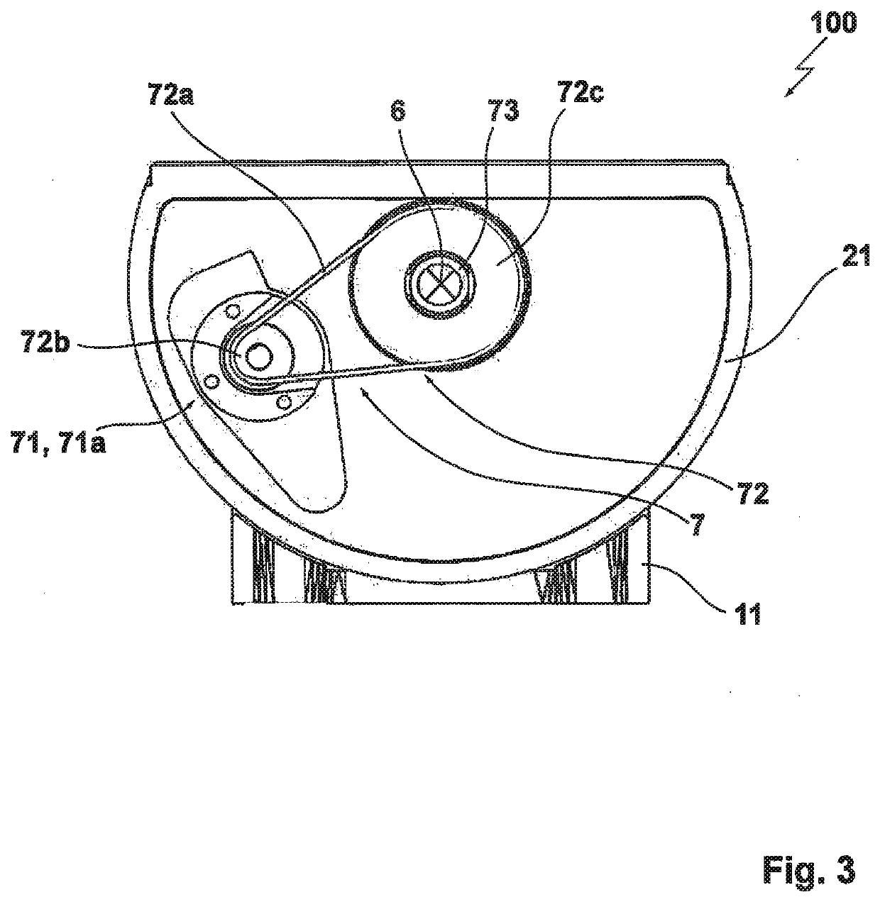
[0024]FIG. 3 a second sectional representation of the embodiment;

[0025]FIG. 4 a third sectional representation of the embodiment; and

[0026]FIG. 5 a schematic representation of an exemplary use of the radar sensor in accordance with the invention for bulk good detection.

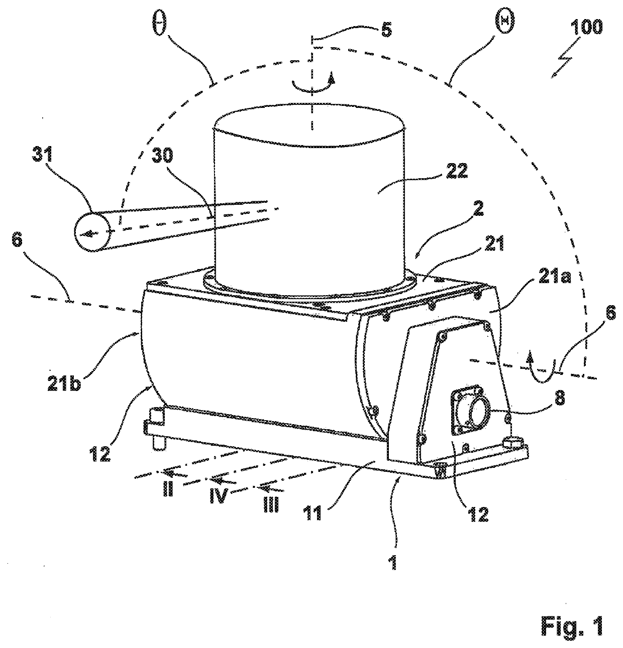
[0027]FIG. 1 shows a schematic representation of an embodiment of the radar sensor 100 in accordance with the invention from which in particular the positional relationships between the radiation direction 30 of the primary signal 31, the axis of rotation 5, and the pivot axis 6 in accordance with the invention can be seen. Both the angle θ between ...


PUM


Abstract

A radar sensor having a frame, a housing arranged at the frame, a transmission and reception unit for high frequency signals arranged within the housing, wherein a radiation direction of the high frequency signals irradiated by the transmission and reception unit is rotatable about an axis of rotation. The radiation direction of the high frequency signals irradiated by the transmission and reception unit is substantially orthogonally oriented toward the axis of rotation, and the housing is supported at the frame rotatably about a pivot axis.

Description

[0001]The present invention relates to a radar sensor comprising a frame, a housing arranged at the frame, a transmission and reception unit for radio frequency signals arranged within the housing, wherein the radiation direction of the radio frequency signals irradiated by the transmission and reception unit is rotatable about an axis of rotation, and wherein the radiation direction of the radio frequency signals irradiated by the transmission and reception unit is substantially orthogonally oriented toward the axis of rotation.PRIOR ART[0002]Radar sensors are apparatus known from the prior art for radio-assisted location and distance measurement on the basis of electromagnetic waves in the radio frequency range, in particular at 5-500 GHz. For this purpose, radar sensors comprise a radio frequency transmitter for irradiating so-called primary signals and a receiver for radio frequency signals that detects the echoes reflected by spaced apart objects as so-called secondary signals....

Claims


Application Information

Patent Timeline
Patent Type & Authority Applications(United States)
IPC IPC(8): G01S7/03
CPCG01S7/03G01S2007/027G01S13/88G01S13/426H01Q1/42H01Q1/1221H01Q3/08H01Q19/132G01S7/027
Inventor WINKEL, REIKHILLEN, FLORIAN
Owner INDURAD
Why Eureka
Try Eureka